
Energy saving glass and a method for making energy saving glass

a technology of energy glass and energy saving glass, which is applied in the field of energy saving glass, can solve the problems of increasing the cost of flat glass production, and not being able to produce a sufficiently thick absorption layer at the flat glass production rate,

Inactive Publication Date: 2013-07-18
BENEQ OY
View PDF2 Cites 0 Cited by
  • Summary
  • Abstract
  • Description
  • Claims
  • Application Information

AI Technical Summary

Benefits of technology

The invention is about an energy saving glass that reduces energy consumption in buildings with cooling systems. The glass has a thin layer on its surface that absorbs solar energy and a low emissivity coating on the other side. The glass can be tempered and used in locations where there are temperature differences on the surface. The method for producing the glass involves growing solar energy absorbing agents on the surface of the glass as nano-sized particles and warmming the glass to allow the metal in the particles to dissolve gradually. The glass can also be coated with a hydrophilic coating, such as titanium dioxide, to improve its ability to transfer heat. Overall, the energy saving glass reduces energy consumption in buildings and is suitable for use in both cooling and heating systems.

Problems solved by technology

However, colouring the glass mass with nonferrous metal oxides is not a very good way of producing energy glasses.
If the entire glass mass is coloured, the glass mass in the glass-melting furnace of a flat glass production line must be regularly changed into clear / coloured glass mass, and changing the colour increases the expenses considerably in flat glass production.
The problem with this glass is that a sufficiently thick absorption layer cannot be produced at the flat glass production rate.
The growth rate provided by CVD process is typically less than 100 nm / s, so the time available for the coating unit (1−2s) does not allow a sufficiently thick layer from the standpoint of the absorption.
Another problem with this solution is that with a thick absorption layer, transmission of the visible light in the glass is considerably reduced.
The problem with this device and method is that the metal oxide layer produced by the spray-pyrolysis method on the surface of the glass dissolves and diffuses quite slowly into the glass.
This provides problems for the long-term endurance, wash resistance and corresponding mechanical and chemical wearing of the coating.
The problem with the method disclosed in the above-mentioned patent is that there are no source materials for these absorbing materials which would by themselves function as flocculent source materials in CVD deposition, so the source materials have to be supplied to the process by means of the high temperature technique described in the patent at the temperature of about 600° C., which requires expensive equipment and expensive operation costs.
A further problem with the method is that the oxides mainly appear as a separate coating on the surface of the glass.
The problem with the structure is that solar radiation energy is absorbed into the glass surface close to the room area, such that the heat transferring by convection from the warm glass is mainly transferred into the room, so the structure does not provide any considerable saving of the cooling energy.
In other words, if the room area is cooled mechanically, more heat transfers from the glass into the interior than into the (warmer) exterior of the building, in which case a large portion of the solar energy absorbing effect of the glass is lost (in view of the cooling requirement).
Such sharp differences provide harmful tensions into the glass.
In these areas, single glazed windows are commonly used, and replacing them with double glazed solutions (separate absorption and low emissivity glasses) is often too expensive a solution.

Method used


Image

  • Energy saving glass and a method for making energy saving glass
  • Energy saving glass and a method for making energy saving glass
  • Energy saving glass and a method for making energy saving glass

Examples


examples

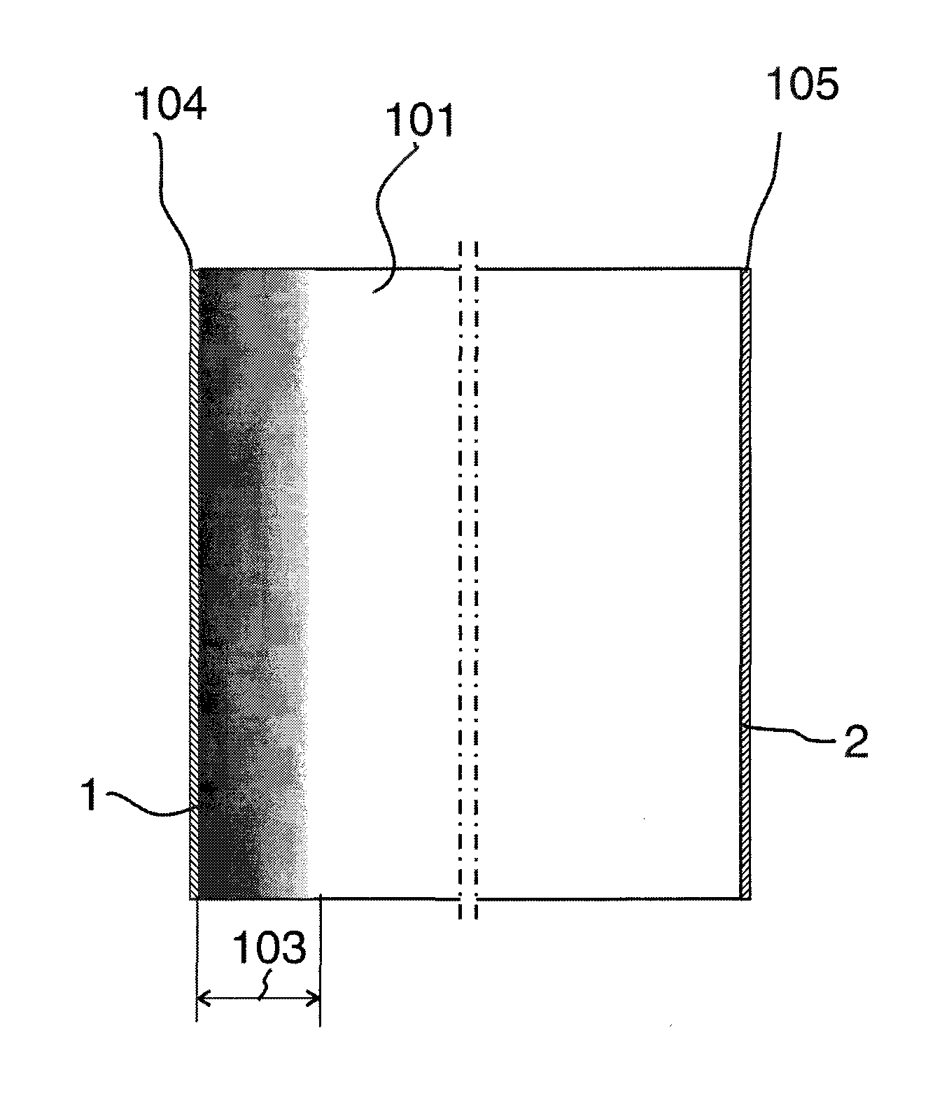
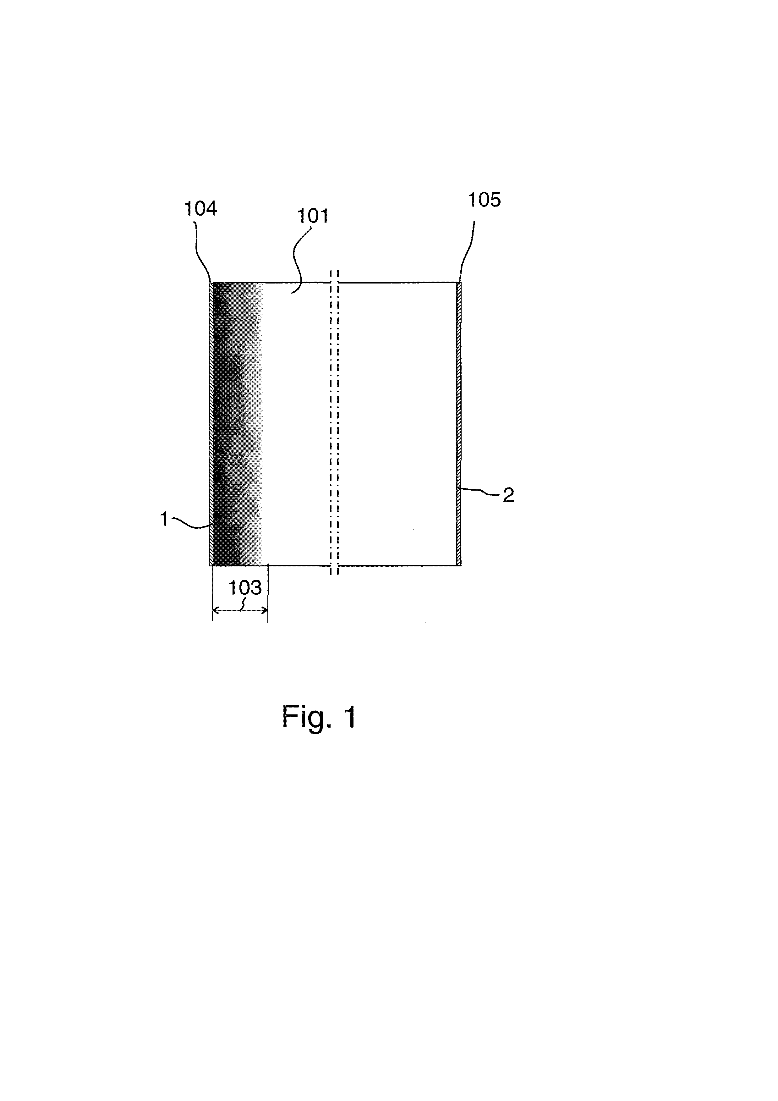
[0050]FIG. 1 shows the energy saving glass according to the invention. A layer of material 104 has been grown on the outer surface 1 of the glass by means of nanoparticles, from which layer the material diffuses and / or dissolves into the glass mass 101, providing an area 103 which is 0.1-100 micrometres deep and in which the metal oxide concentration of the glass gradually decreases when proceeding from the surface 1 deeper into the glass, which is illustrated in FIG. 1 as the area shifting from dark to white. This gradual layer 103 provides at least partial absorption of solar energy into the surface layer of the glass. It is possible to grow a low emissivity coating 105 on the inner surface 2 of the glass 101, or coat the glass before growing the absorption layer with such coating, which may be for example a coating made from Transparent Conductive Oxide (TCO).

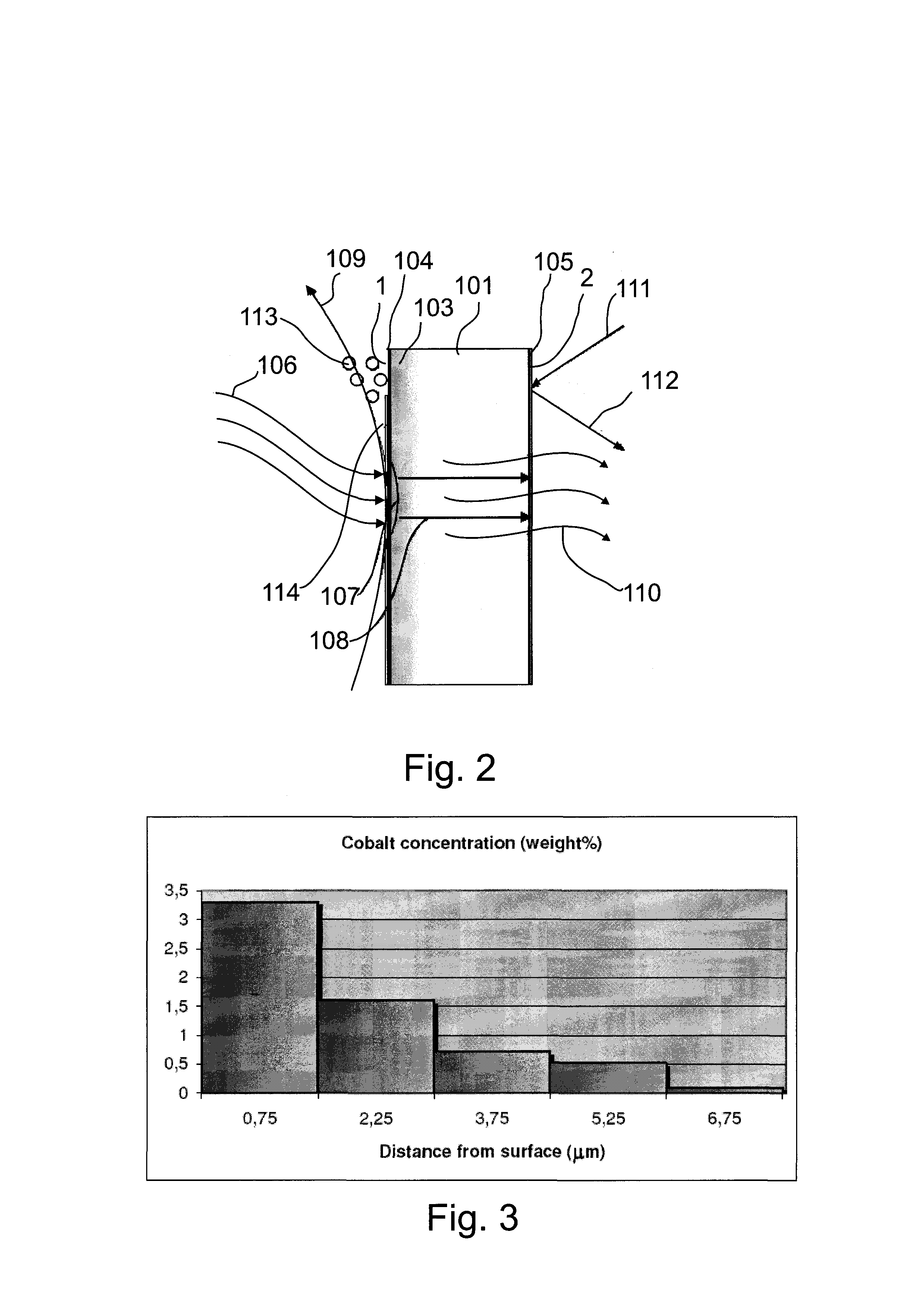
[0051]FIG. 2 shows the behaviour of the energy saving glass of FIG. 1. Energy 106 from the sun is absorbed at least partly...


PUM

PropertyMeasurementUnit
temperatureaaaaaaaaaa
thicknessaaaaaaaaaa
aerodynamic diameteraaaaaaaaaa

Abstract

The energy saving glass comprises a substantially mutually parallel first surface and second surface, and the glass mass of the energy saving glass contains a solar radiation energy absorbing agent. The solar radiation energy absorbing agent is present in a layer of the glass mass which is close to the first surface, in which layer the concentration of the radiation energy absorbing agent substantially decreases when proceeding from the first surface deeper into the glass mass, such that the absorbing agent is present at the depth of at least 0.1 micrometres and not more than 100 micrometres as measured from the first surface of the glass. In the method, a layer of particulates is grown on the first surface of the glass, which particulates include at least one element or compound of the elements and diffuse and / or dissolve into the surface layer of the glass. At least one element dissolving from the particulates modifies the surface layer of the glass such that the solar radiation energy absorbing layer is formed on the surface, in which layer the concentration of said at least one element substantially decreases from the surface of the glass deeper into the glass, such that the element is present at the depth of at least 0.1 micrometres and not more than 100 micrometres as measured from the surface of the glass.

Description

FIELD OF THE INVENTION[0001]The invention relates to the energy saving glass defined in the preamble of claim 1. Furthermore, the invention relates to the method defined in the preamble of claim 17.BACKGROUND OF THE INVENTION[0002]When solar radiation energy meets a glass surface, some of the radiation is reflected, some of it is absorbed into the glass and some of it penetrates the glass. In a normal window glass, the absorption is scarce. The solar radiation that penetrates the window is absorbed into the surfaces and objects in the interior of the building, which warm and release the heat further into the interior. In areas with a high degree of solar radiation, the heat causes the need for cooling the room areas. Buildings are great energy-consumers, for example in the North America, heating, cooling and lighting of buildings make up 30-40% of all energy. Therefore technical solutions which reduce the need for cooling and heating buildings, and windows which bring as much natura...

Claims


Application Information

Patent Timeline
Patent Type & Authority Applications(United States)
IPC IPC(8): C03C21/00
CPCC03C17/245C03C17/2453C03C17/2456C03C21/007C03C2217/212C03C2217/216Y10T428/265C03C2217/75C03C2217/944C03C2217/948C03C2218/15C03C2218/365C03C21/008C03C2217/231C03C17/22C03C17/3411
Inventor RAJALA, MARKKUPIMENOFF, JOEDECROUPET, DANIEL
Owner BENEQ OY
Learn More