
Anti-fogging and air-conditioning system for electric vehicle, dehumidifying unit, dehumidifying cassette, and dehumidifying member

a technology for electric vehicles and air conditioners, which is applied in the direction of vehicle maintenance, vehicle cleaning, separation processes, etc., can solve the problems of system useless as a measure against the decrease of running mileage of electric vehicles, and insufficient reduction of relative humidity of air,

Inactive Publication Date: 2013-07-18
WATANABE TAKUMASA
View PDF40 Cites 11 Cited by
  • Summary
  • Abstract
  • Description
  • Claims
  • Application Information

AI Technical Summary

Benefits of technology

The present invention is an anti-fog and HVAC system for electric vehicles that uses a chemical water vapor adsorbing phenomenon to reduce power consumption and is small and lightweight, excellent in usability, and economical. The system has a window anti-fog effect and a vehicle heating effect that reduces the need for electric power. This invention is designed to provide improved safety and comfort for electric vehicle drivers and passengers.

Problems solved by technology

Therefore, there are such problems that the system is upsized, and, particularly in the case where the outside air temperature decreases, the relative humidity of air is not sufficiently reduced, which may therefore require additional air heating by electric power from the electric storage device.
Therefore, this system is useless as a measure against running mileage decrease in the electric vehicle.
However, the heat storage amount is limited, and hence there is a problem in that, although warm air can be produced at an initial stage of electric vehicle driving, support cannot be made for a long period of time.
As the heat storage body, there are known paraffins and an inorganic hydrated salt, which have a melting point lower than about 80° C. However, due to the limitation of the in-vehicle space, it is difficult to obtain a sufficient heat storage capacity, and the price is unset yet.
Thus, this technology is still impractical.

Method used


Image

  • Anti-fogging and air-conditioning system for electric vehicle, dehumidifying unit, dehumidifying cassette, and dehumidifying member
  • Anti-fogging and air-conditioning system for electric vehicle, dehumidifying unit, dehumidifying cassette, and dehumidifying member
  • Anti-fogging and air-conditioning system for electric vehicle, dehumidifying unit, dehumidifying cassette, and dehumidifying member

Examples


first embodiment

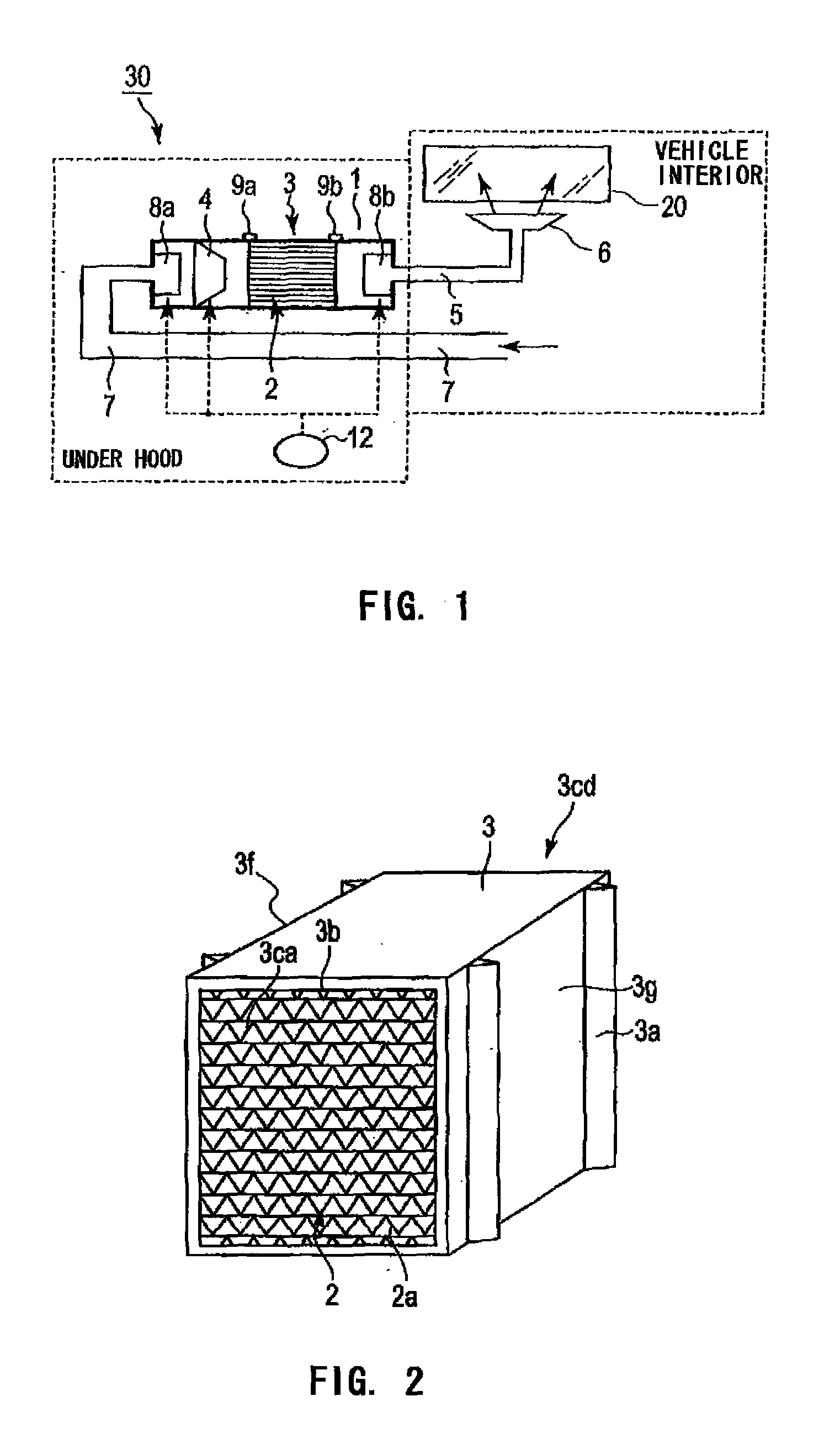
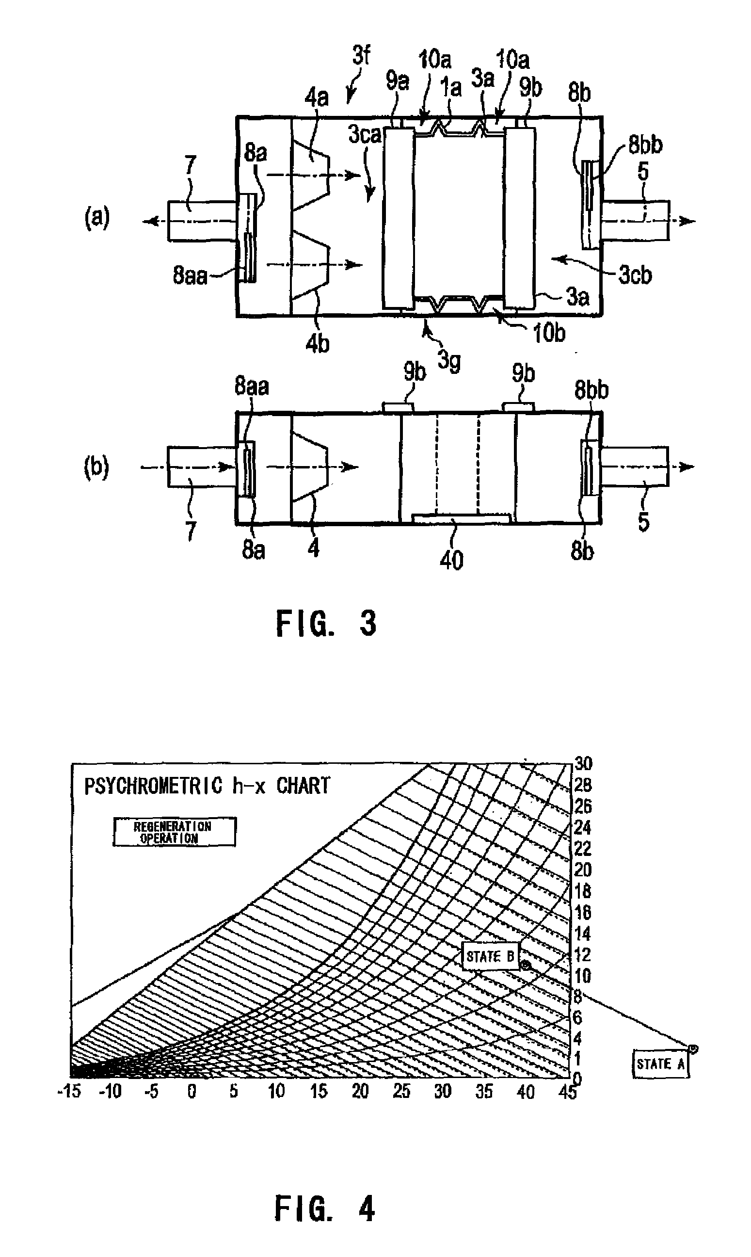
[0080]FIG. 1 is a configuration diagram of an anti-fog and HVAC system 30 provided in an electric vehicle according to a first embodiment of the present invention. The anti-fog and HVAC system 30 includes a dehumidifying unit 1, a dehumidifying cassette (hereinafter referred to as “cassette”) 3 provided inside the dehumidifying unit 1, the cassette containing a dehumidifying member 2, a blower fan 4, a ventilation duct 5 provided on the air exiting side of the dehumidifying unit 1, an anti-fog nozzle 6 provided downstream of the ventilation duct 5, for blowing air that has passed through the anti-fog nozzle 6 toward a front window 20, an interior air inlet duct 7 provided on the air entering side of the dehumidifying unit 1, upstream side drive valve portion 8a and downstream side drive valve portion 8b for preventing air from flowing into the dehumidifying unit 1 when the system is not used, and a fixing member 9 (upstream side fixing member 9a and downstream side fixing member 9b)...

second embodiment

[0108]FIG. 6 is a configuration diagram of an anti-fog and HVAC system for an electric vehicle according to a second embodiment of the present invention. The dehumidifying unit 1 includes a sensor 11 for detecting the change of the absolute weight of the cassette 3 containing the dehumidifying member 2 when the cassette 3 moves along the cassette guide grooves la. The sensor 11 is provided in the space region 40. Further, the sensor 11 detects the change of weight in several milligrams (for example, the sensor 11 is a member such as a spring plate).

[0109]The cassette guide groove la for introducing the cassette 3 has a shape that allows free movement of the cassette 3 in the gravity direction. As the dehumidifying member 2 in the cassette 3 absorbs moisture and increases its weight, the weight change is detected by the sensor 11. That is, the spring of the sensor 11 contracts by the weight.

[0110]When the casset 3 descends by the weight change of the cassette 3, a sensor 13 is activa...

third embodiment

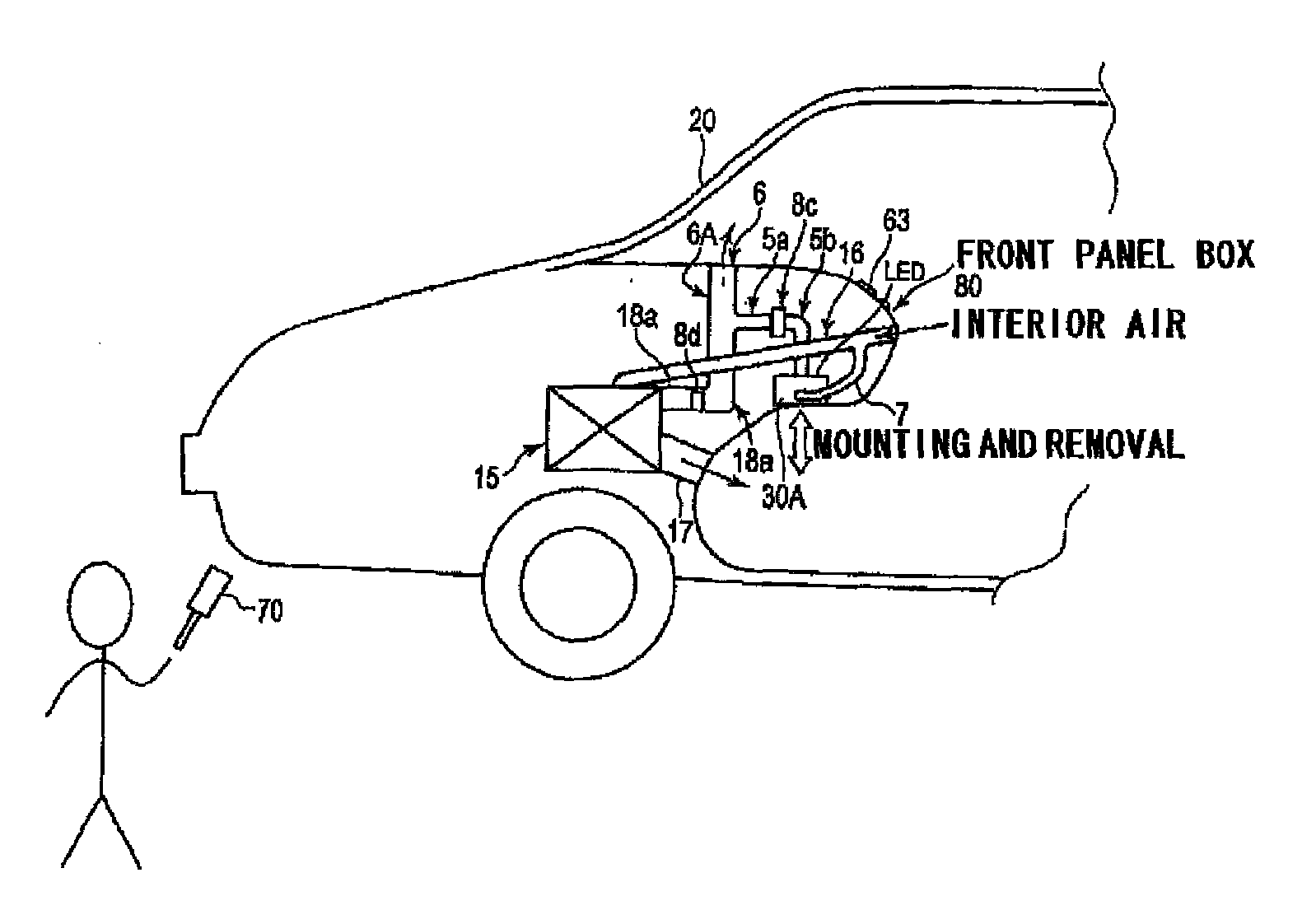
[0111]FIG. 7 is a schematic configuration diagram of an anti-fog and HVAC system for an electric vehicle according to a third embodiment of the present invention. FIG. 7 is a diagram of a case where the anti-fog and HVAC system 30 for an electric vehicle is provided in a ceiling portion of a passenger compartment (or a luggage compartment) of the electric vehicle.

[0112]In this case, the dehumidifying unit 1 is mounted in a state turned upside down from the state illustrated in FIG. 3, and the cassette 3 is replaced from a lower surface side of the dehumidifying unit 1. Therefore, the fixing device 9 is provided on the lower surface portion of the dehumidifying unit 1, and the sensors 11 and 13 (also referred to as weight detection device) of the cassette 3 are mounted on the fixing device 9 side.

[0113]In the electric vehicle having the anti-fog and HVAC system 30 provided in the ceiling portion of the passenger compartment (or the luggage compartment) of the electric vehicle, the an...


PUM

PropertyMeasurementUnit
Temperatureaaaaaaaaaa
Currentaaaaaaaaaa
Digital informationaaaaaaaaaa

Abstract

Provided is an anti-fog and HVAC system (30, 30A, 30B) for an electric vehicle, which is configured to dehumidify air inside the electric vehicle, the anti-fog and HVAC system including: a unit casing (1K) formed into a rectangular parallelepiped shape with a hollow interior, the unit casing (1K) containing a dehumidifying unit (1) removably storing a dehumidifying cassette (3) containing a dehumidifying member (2); an inlet duct (7) for guiding the air inside the electric vehicle to an input side of the unit casing (1K); and a ventilation duct (5) for discharging, into the electric vehicle, dehumidified air from an output side of the unit casing (1K).

Description

TECHNICAL FIELD [0001]The present invention relates to an anti-fog and heating, ventilation, and air conditioning (HVAC) system for an electric vehicle, a dehumidifying unit, a dehumidifying cassette, and a dehumidifying member, which are configured to dehumidify air inside the electric vehicle.BACKGROUND ART [0002]In recent years, global warming trend has become more pronounced. As part of measures to the global warming, efforts have been made to introduce electric vehicles which use absolutely no fossil fuel during running, in order to reduce emissions of carbon dioxide, which is a major greenhouse gas.[0003]However, the electric vehicles have the following problems. For example, water condensation due to water vapor (insensible perspiration) of a passenger occurs on the glass windows when the outside air temperature is lower than the inside temperature. Such water condensation can obstruct the driver's view.[0004]In order to solve this problem, dehumidification of air around the ...

Claims


Application Information

Patent Timeline
IPC IPC(8): B60S1/02B60H1/32
CPCB01D53/261B01D2253/102B01D2253/106B01D2253/108B01D2253/202B60S1/023B01D2258/06B01D2259/4566B60H3/024B60H2003/026B60H1/3207B01D2257/80B60H3/00B60H1/34B01D53/26
Inventor WATANABE, TAKUMASA
Owner WATANABE TAKUMASA
Learn More