Micromechanical resonator and method for manufacturing thereof

Active Publication Date: 2013-07-25
TEKNOLOGIAN TUTKIMUSKESKUS VTT OY
View PDF2 Cites 20 Cited by
  • Summary
  • Abstract
  • Description
  • Claims
  • Application Information

AI Technical Summary

Benefits of technology

[0027]One particular advantage of the invention is that resonance mode having a saddle point can be excited to the resonator using piezoelectric transducing means, such as a piezoelectric thin film deposited on top of the resonator element. This is in contrast with for example torsional beam resonators, which cannot be excited in a similar way. Thus, disadvantages with regard to e.g. bias voltage requirements and gaps between the resonator element and transducers are completely avoided.
[0028]A saddle mode also inherently has nodal points at the perimeter of the resonator element which can be used as low-loss anchoring poi

Problems solved by technology

However, the production process for producing crystal resonators is different from the process of producing most other electrical circuits, which are mainly produced of silicon.
The quartz crystal components also tend to be large in size.
One problem associated with silicon based resonators is that they have a high temperature drift of the resonance frequency.
It is possible to compensate the temperature dependence with a temperature sensor and related electronic control circuitry, but it has not been possible to provide a resonator with sufficiently low temperature drift with low cost technology which would be suitable for mass production applications and would compete with quartz quality.
Also, the use of a temperature compensation circuit increases the consumption of energy, which is a significant disadvantage especially in battery operated devices.
Further, the compensation circuit tends to increase electric noise in the resonator circuit.
However, this solution also increases the energy consumption and noise of the device, and makes the device complicated to produce.
The temperature compensation circuits are also slow in controlling, and cannot therefore compensate fast or large changes in ambie

Method used


Image

  • Micromechanical resonator and method for manufacturing thereof
  • Micromechanical resonator and method for manufacturing thereof
  • Micromechanical resonator and method for manufacturing thereof

Examples


Embodiment Construction

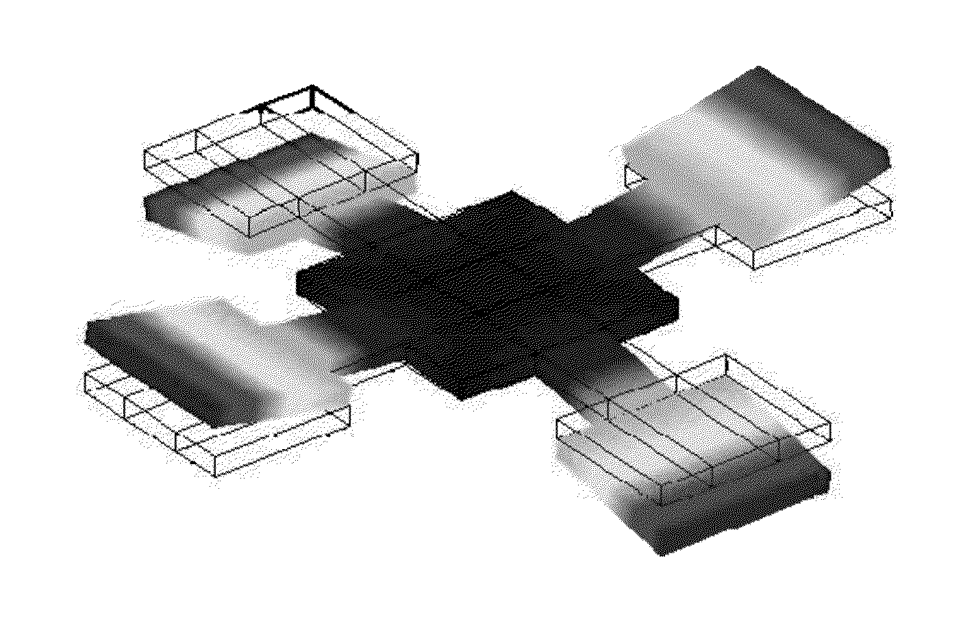
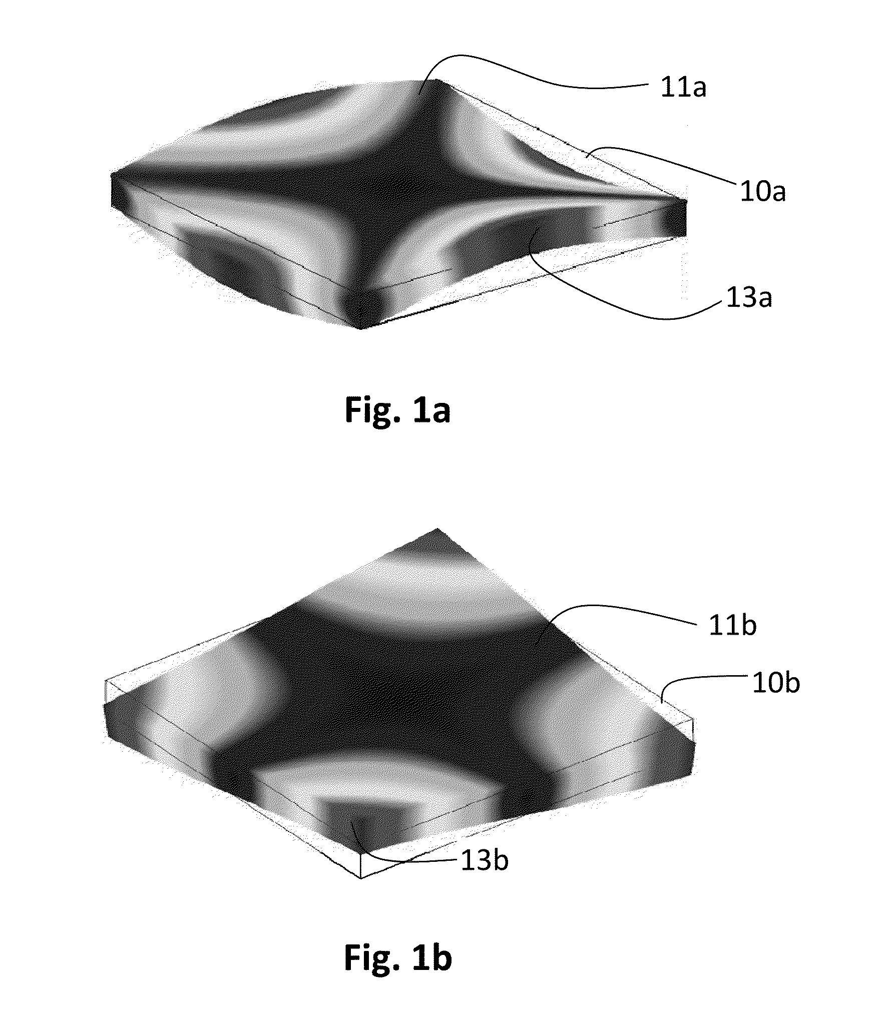
[0041]The invention is now described in more detail having particular focus on rectangular saddle mode resonators and shortly introducing other preferred shapes too. However, first the concept of c44 dependency of the frequency of a resonator made of silicon and particular advantages of the invention with respect to temperature compensation are described in more detail.

[0042]The resonance frequency of a mode of a resonator having an arbitrary shape is, in a general form, given by

f=A1Lcρ,(Eq.A)

where c is a generalized elastic modulus of the material, ρ is the material density, and L is a generalized dimension of the resonator. For single crystal silicon, the elastic properties are given by three independent elastic parameters c11, c12 and c44, and the generalized elastic modulus c is a function of the three elastic parameters

c=c(c11,c12,c44).  (Eq. B)

[0043]Importantly, constant A depends on the resonator geometry, on the resonator relative orientation with the silicon crystal axes, a...


PUM

PropertyMeasurementUnit
Fractionaaaaaaaaaa
Temperatureaaaaaaaaaa
Forceaaaaaaaaaa

Abstract

The invention relates to a temperature compensated micromechanical resonator and method of manufacturing thereof. The resonator comprises a resonator element comprising a semiconductor crystal structure, which is doped so as to reduce its temperature coefficient of frequency, transducer means for exciting to the resonator element a vibrational mode. According to the invention the crystal orientation and shape of the resonator element are chosen to allow for a shear mode having a saddle point to be excited to the resonator element, and said transducer means are adapted to excite said shear mode to the resonator element. Accurate micromechanical resonators with now temperature drift can be achieved by means of the invention.

Description

FIELD OF THE INVENTION[0001]The invention relates to micromechanical resonators and a method for producing the same. In particular, the invention relates to temperature compensated silicon resonators according to the preamble of claim 1.BACKGROUND OF THE INVENTION[0002]Resonators are commonly used in electronics for providing a signal with accurate and stable frequency. The resonators are mostly made using quartz crystals, which have a good accuracy and temperature stability of frequency. However, the production process for producing crystal resonators is different from the process of producing most other electrical circuits, which are mainly produced of silicon. Therefore, the quartz crystal resonators are usually separate components, whereby separate phases are required in the production process of electronic devices.[0003]The quartz crystal components also tend to be large in size. It would be desirable to provide MEMS resonators made of silicon or other semiconductor materials i...

Claims


Application Information

Patent Timeline
IPC IPC(8): H03H9/19H03H3/013
CPCH03H9/02448H03H2009/02496H03H2009/2442Y10T29/41H03H9/19H03H2009/02511H03H2009/02519H03H3/013B81B3/0081H03H9/02102
Inventor JAAKKOLA, ANTTIPENSALA, TUOMAS
Owner TEKNOLOGIAN TUTKIMUSKESKUS VTT OY
Why Eureka
Try Eureka