Thin film optical filters with an integral air layer

a technology of optical filters and air layers, applied in the field of optical filters, can solve the problems of optical filters often not producing satisfactory, undesirable polarization effects, and low polarization efficiency, and achieve the effects of reducing cost, effective control of polarization effects, and convenient fabrication

Inactive Publication Date: 2013-07-25
NAT RES COUNCIL OF CANADA
View PDF3 Cites 16 Cited by
  • Summary
  • Abstract
  • Description
  • Claims
  • Application Information

AI Technical Summary

Benefits of technology

[0013]The embodiments of the invention effectively control the polarization effects with an integral air layer in thin film optical filters that operate at oblique angles greater than the critical angle. The air layer which is defined by a spacer layer permits the easy fabrication of high-performance thin film optical filters with reduced cost. In addition, compared to traditional thin film optical filter having all solid films, these embodiments have much improved performances, or smaller prism size because the angles of incidence can be reduced with the use of low index air layer, or reduced total number of layers or layer thickness, or all of the above.

Problems solved by technology

One arising issue with optical filters used at oblique angles of incidence is the polarization effect for s- and p-polarized light due to their different optical admittances at oblique angles.
For many other optical filters such as non-polarizing beam-splitters, cut-off filters and bandpass filters, the polarization effect is not desirable and must be minimized.
Using thin film interference effect alone to either enhance or minimize polarization effect in these optical filters often does not produce satisfactory results.
However, it has been demonstrated that the phenomenon of frustrated total internal reflection can be combined with thin film interference to successfully control the polarization effect in polarizing and non-polarizing thin film beam-splitters.
There are several problems with using the FTIR effect in thin film optical filters having solid layers.
First, because the selection of low index coating materials is limited and the refractive index values are not as low as one would prefer, usually 1.38 for MgF2 and 1.45 for SiO2, which leads to a very large critical angle θC.
The large θC will result in large working angles for the thin film optical filters, which in turn results in large size filters.
Large size optical filters are not desirable for many applications.
Second, although the critical angle can be reduced by using high index substrates (for example, n0>1.60), more, complicated or expensive optical bonding technique have to be used to cement the two substrates together.
It is generally very difficult to bring two coated high refractive index prisms into good contact.
Index matching optical cements, which are commonly used in the optics industry, are not suitable for this purpose because stable and highly transparent (transmittance>95%) optical cement with a refractive index greater that 1.60 is not available.
Refractive index-matching liquids are also not suitable because they are usually not stable and require proper sealing and thickness control.
Thus, the only suitable optical bonding technique is very expensive optical contacting.
This strict flatness requirement increases the manufacturing cost.
Poor coating quality such as roughness can further reduce the success rates of optical contacting.
The difficulty of achieving a good optical contact is directly proportional to the area of the surfaces to be contacted.
The larger the component surfaces, the more difficult it is to make their surfaces sufficiently flat and smooth for optical contact.
In addition, for optical filters in the infrared spectral region, because the optical filters are much thicker compared to the visible spectral region, the filter coatings are usually deposited by a much faster evaporation process that inherently produces rough and porous films, making optical contacting even more difficult.

Method used


Image

  • Thin film optical filters with an integral air layer
  • Thin film optical filters with an integral air layer
  • Thin film optical filters with an integral air layer

Examples


Embodiment Construction

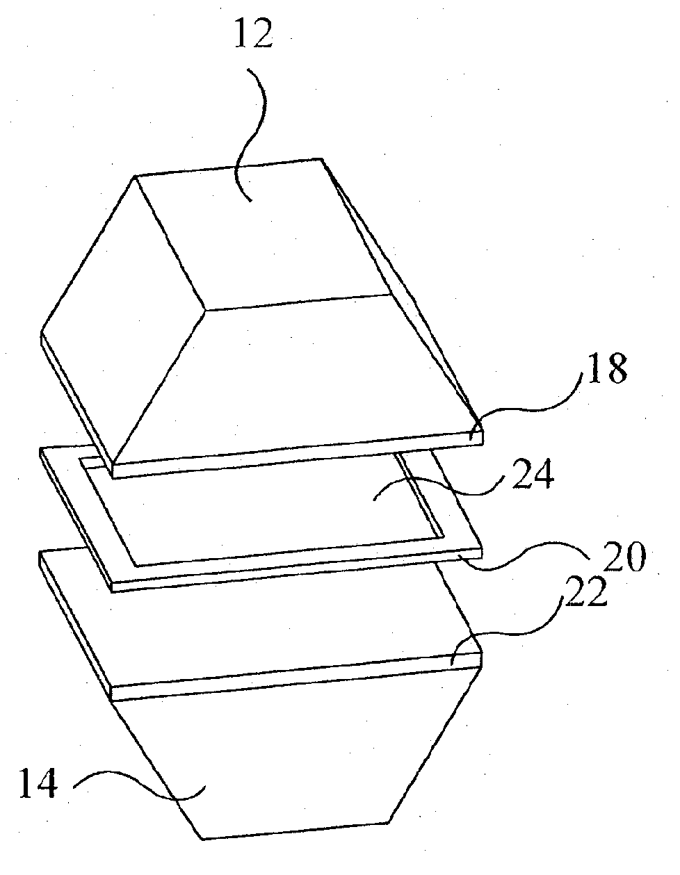
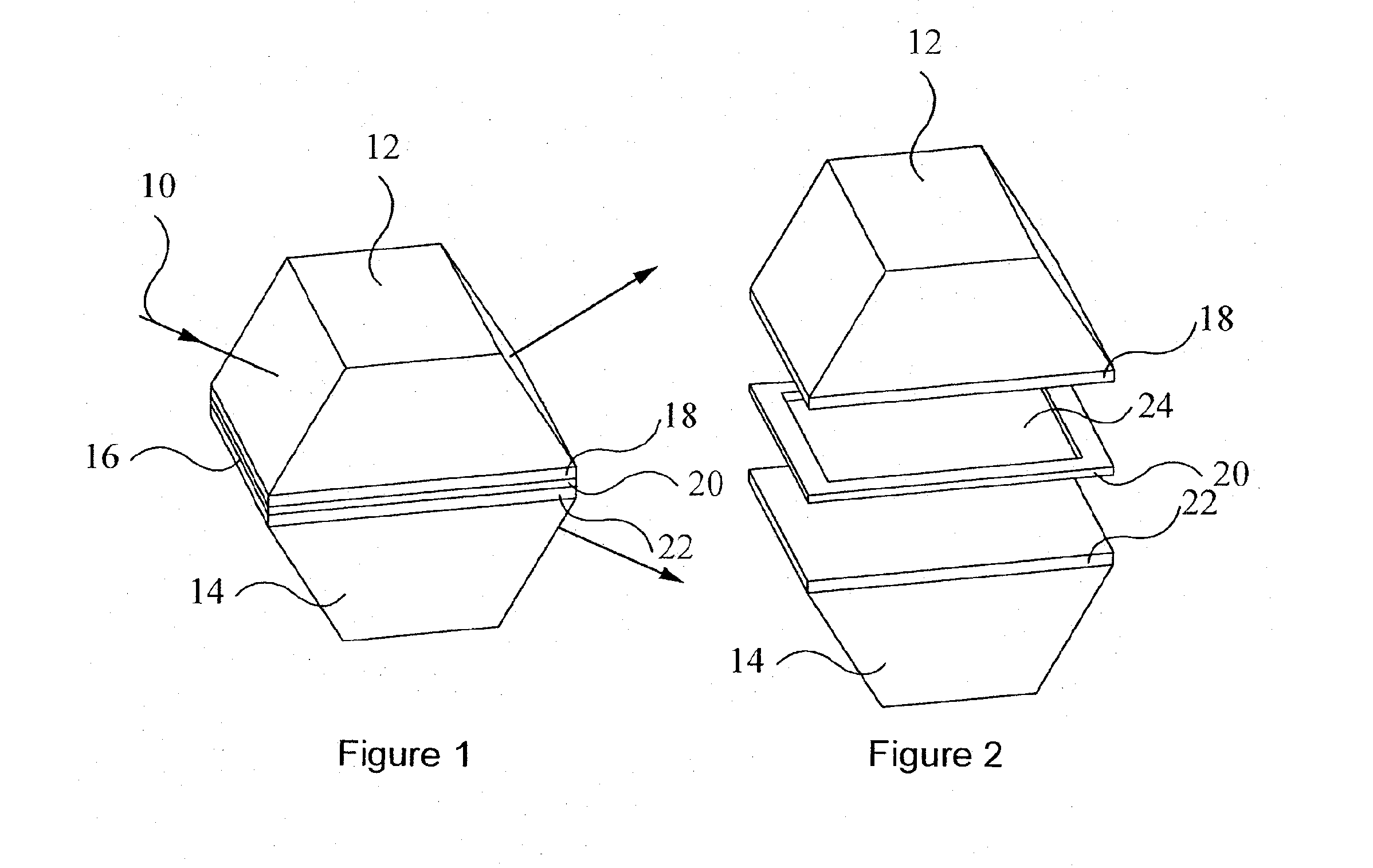
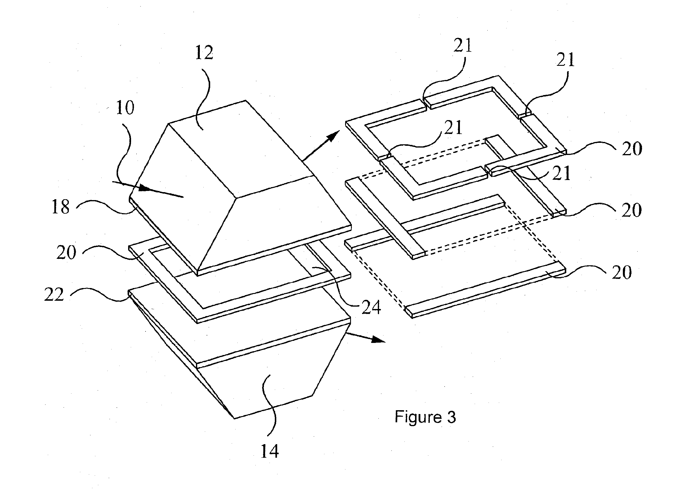
[0052]The layouts the novel thin film optical filters with an integral air layer will be explained with reference to FIGS. 1 to 4. When incident light 10 is incident at the thin film coating surface at an oblique angle, some of the incident light will be reflected and some will be transmitted according to the filter requirements.

[0053]As shown in FIGS. 1 to 4, the thin film optical filter has a transparent top-prism 12 and a transparent bottom-prism 14 having a refractive index n0 and a thin film coating structure 16 at the interface between the two prisms. The thin film coating structure 16 consists of a top coating 18, a spacer layer 20 and an optional bottom coating 22. The spacer layer 20 bounds a cavity containing an air layer 24, also referred to herein as the cavity layer. The top- and bottom-coatings 18, 22 together with the air layer 24 form a complete thin film interference coating structure. The air layer 24 acts as an interference layer within the complete thin film stru...


PUM

PropertyMeasurementUnit
refractive indexaaaaaaaaaa

Abstract

Novel thin film optical filters have an integral air layer. The frustrated total internal reflection (FTIR) phenomenon, combined with thin film interference, is used to effectively control the polarization properties of thin film coatings operating at oblique angles. The invention is applicable to high-performance thin film polarizing beam-splitters, non-polarizing beam-splitters, non-polarizing cut-off filters and non-polarizing band-pass filters, and any other thin film coatings that require the control of polarization effect. The low index layer offers an improvement in performance and the simplification of the thin film optical filter coating designs by reducing the total number of layers and the total layer thicknesses to minimize the angles of incidence and the size of the filter substrates, thereby minimizing the contact area and hence reducing the manufacturing costs.

Description

FIELD OF THE INVENTION[0001]This invention relates to the field of optical filters, and in particular optical filters employing thin film interference and frustrated total internal reflection (FTIR).BACKGROUND OF THE INVENTION[0002]Thin film optical filters are often used in applications that require light incident at the filter surfaces at non-normal or oblique angles of incidence in order to generate two beams: a reflected beam and a transmitted beam. Such optical filters include thin film polarizing beam-splitters, non-polarizing beam-splitters, long-wavelength and short-wavelength cut-off filters, bandpass filters, etc. Often these thin film optical filters consist of multiple layers between two solid glass substrates or prisms. One arising issue with optical filters used at oblique angles of incidence is the polarization effect for s- and p-polarized light due to their different optical admittances at oblique angles. This polarization effect is manifested as different filter pr...

Claims


Application Information

Patent Timeline
Patent Type & Authority Applications(United States)
IPC IPC(8): G02B5/28
CPCG02B5/284G02B27/1073Y10T156/10G02B27/144G02B27/283G02B27/142
Inventor LI, LIDOBROWOLSKI, JERZY A.
Owner NAT RES COUNCIL OF CANADA
Why Eureka
Try Eureka