
Atmospheric humidity or temperature or cloud height measuring method and apparatus

a technology of atmospheric humidity or temperature and height measurement, applied in the direction of lasers, using reradiation, using multiple variables to indicate weather conditions, etc., can solve the problems of unsatisfactory signal-noise ratio, method sluggishness, and high cost of lasers, so as to achieve precise stabilization results, simple mechanical means, and improved signal-noise ratio of atmospheric measurements.

Active Publication Date: 2013-08-01
VAISALA
View PDF5 Cites 6 Cited by
  • Summary
  • Abstract
  • Description
  • Claims
  • Application Information

AI Technical Summary

Benefits of technology

The invention is about using an interference filter to stabilize the power of a laser when transmitting through clouds. This improves the accuracy and signal-to-noise ratio of the measurements made. The technical effect of using the interference filter is that it helps to concentrate the laser power in a narrow measuring band, resulting in more reliable and accurate data. Additionally, the invention can be easy to implement using a tiltable interference filter and simple mechanical means.

Problems solved by technology

A drawback in the prior art is that, despite its good properties, the method is sluggish, due to the non-ideal properties of the transmitting diode laser.
Due to the broad band and instability, the signal-noise ratio has been unsatisfactory.
Such lasers are extremely expensive and, due to the single mode, the output takes place in a linear spectrum, which, in some measurement applications, is hypersensitive to the measuring variables or the properties of the atmosphere.

Method used


Image

  • Atmospheric humidity or temperature or cloud height measuring method and apparatus
  • Atmospheric humidity or temperature or cloud height measuring method and apparatus
  • Atmospheric humidity or temperature or cloud height measuring method and apparatus

Examples


Embodiment Construction

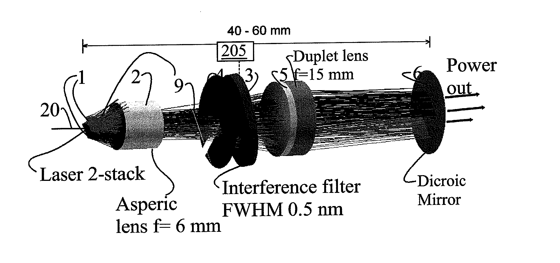
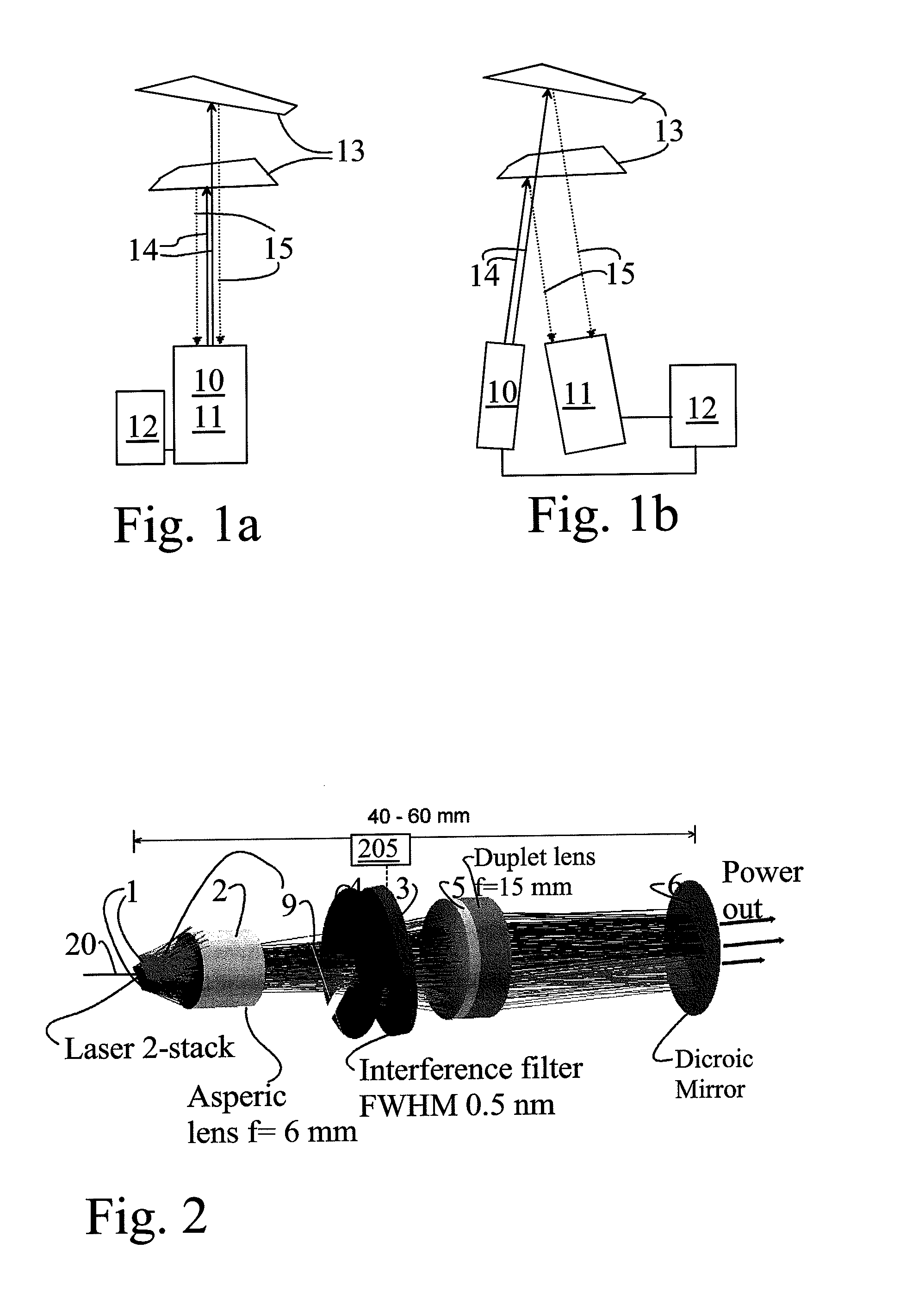
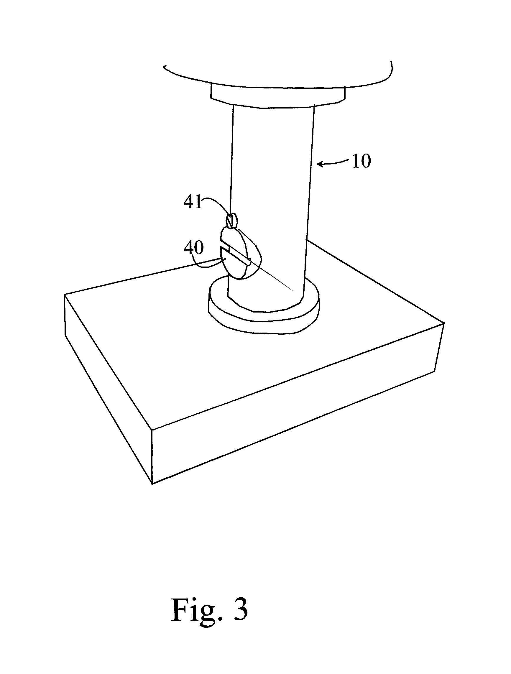
[0027]According to FIG. 1a, the humidity profile and / or temperature and / or cloud height measuring device comprises common transmission and reception optics 10 and 11, from which, with the aid of transmission optics 10 and a light source, laser pulses 14 are sent to the atmosphere and are reflected or scattered back from clouds or other aerosols or molecules 13 back to the detection optics and apparatus 11. The control and measurement logic 12 determines the delays and strengths of the transmitted and received radiation and on their basis the height of the clouds 13 or correspondingly the humidity profile or temperature profile is calculated. The optics according to FIG. 1a can be implemented, for example, coaxially, in which case transmission will take place from the centre of the optics and reception from the circumference of the same optics, or alternatively the locations of the transmission and reception can change places. Instead of being coaxial, transmission and reception can ...


PUM


Abstract

An atmospheric cloud height, humidity profile, or temperature measuring method and arrangement are provided. In the method, pulsed laser signals (14) are transmitted through transmission optics (2, 3, 4, 5, 6) to the atmosphere and the signal (15) reflected or scattered back from there is detected. An interference filter (3) is used in the optics, in order to stabilize the transmitted optical power to the centre wavelength of the interference filter (3).

Description

BACKGROUND OF THE INVENTION[0001]1. Field of the Invention[0002]The present invention relates to a cloud-probing apparatus. The invention also relates to an atmospheric humidity profile or temperature profile or cloud height measuring apparatus.[0003]2. Brief Description of the Prior Art[0004]According to the prior art, semiconductor pulse lasers (pulsed diode lasers) are used for cloud probing. In these solutions, the laser's entire wavelength band is sent to the object being measured and the backscattered light is detected. In the detection of the backscattered signal, either completely separate detector optics is used, or alternatively partly the same optics has operated in both the transmission and in the detection.[0005]A drawback in the prior art is that, despite its good properties, the method is sluggish, due to the non-ideal properties of the transmitting diode laser. The transmission power of a pulsed diode laser is spread over a wide wavelength range. At high transmission...

Claims


Application Information

Patent Timeline
IPC IPC(8): G01S17/95
CPCG01K2213/00G01S17/95G01W1/00G01S7/4815G02B26/001H01S5/4062G01S7/4814G02B5/28Y02A90/10G01W1/02H01S3/137
Inventor KALLIO, JUKKA
Owner VAISALA
Learn More