Filling of a volume accumulator in a camshaft adjuster

a technology of volume accumulator and camshaft adjuster, which is applied in the direction of multiple way valves, check valves, functional valve types, etc., can solve the problems of loss of hydraulic tension, unstable behaviour of the camshaft adjuster as a whole, and rotational speed-dependent filling

Inactive Publication Date: 2013-08-08
SCHAEFFLER TECH AG & CO KG
View PDF6 Cites 8 Cited by
  • Summary
  • Abstract
  • Description
  • Claims
  • Application Information

AI Technical Summary

Benefits of technology

[0018]In another refinement, the specified control piston comprises a switch for closing off the passage. By means of the switch, the volume accumulator, after being filled with hydraulic liquid, can be separated from the pressure port such that the hydraulic fluid stored in the volume accumulator is stored at a lower pressure than the pressure that has been built ...

Problems solved by technology

Due to the centrifugal force, however, the filling is rotational-speed-dependent.
This air which is drawn in ...

Method used


Image

  • Filling of a volume accumulator in a camshaft adjuster
  • Filling of a volume accumulator in a camshaft adjuster
  • Filling of a volume accumulator in a camshaft adjuster

Examples


Embodiment Construction

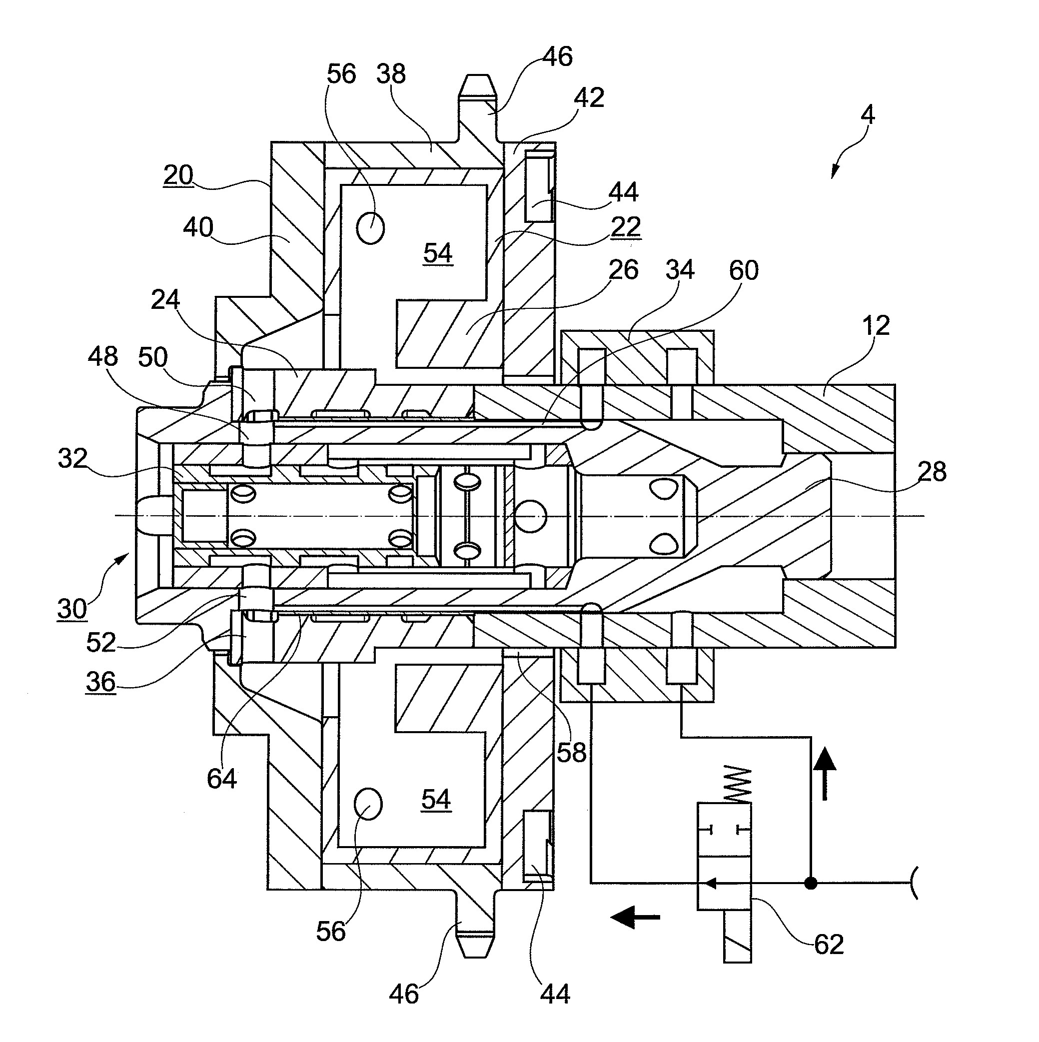
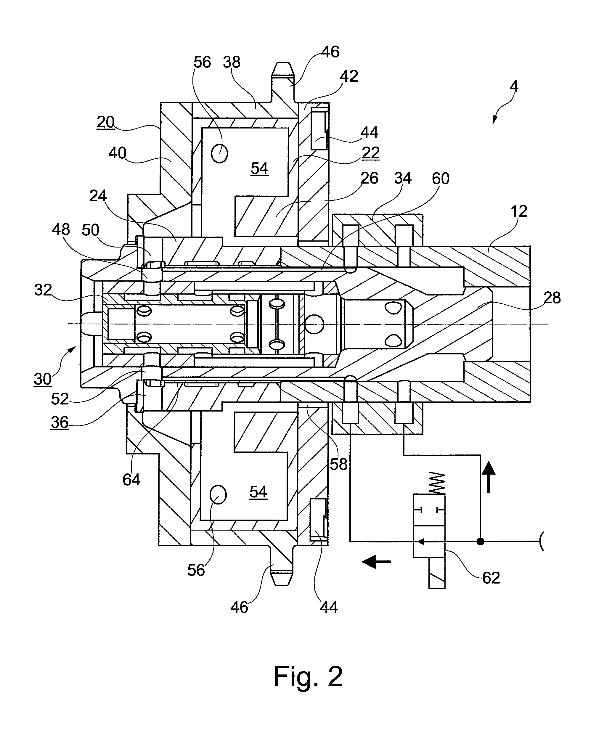
[0032]In the Figures, identical elements are denoted by the same reference numerals and will be described only once.

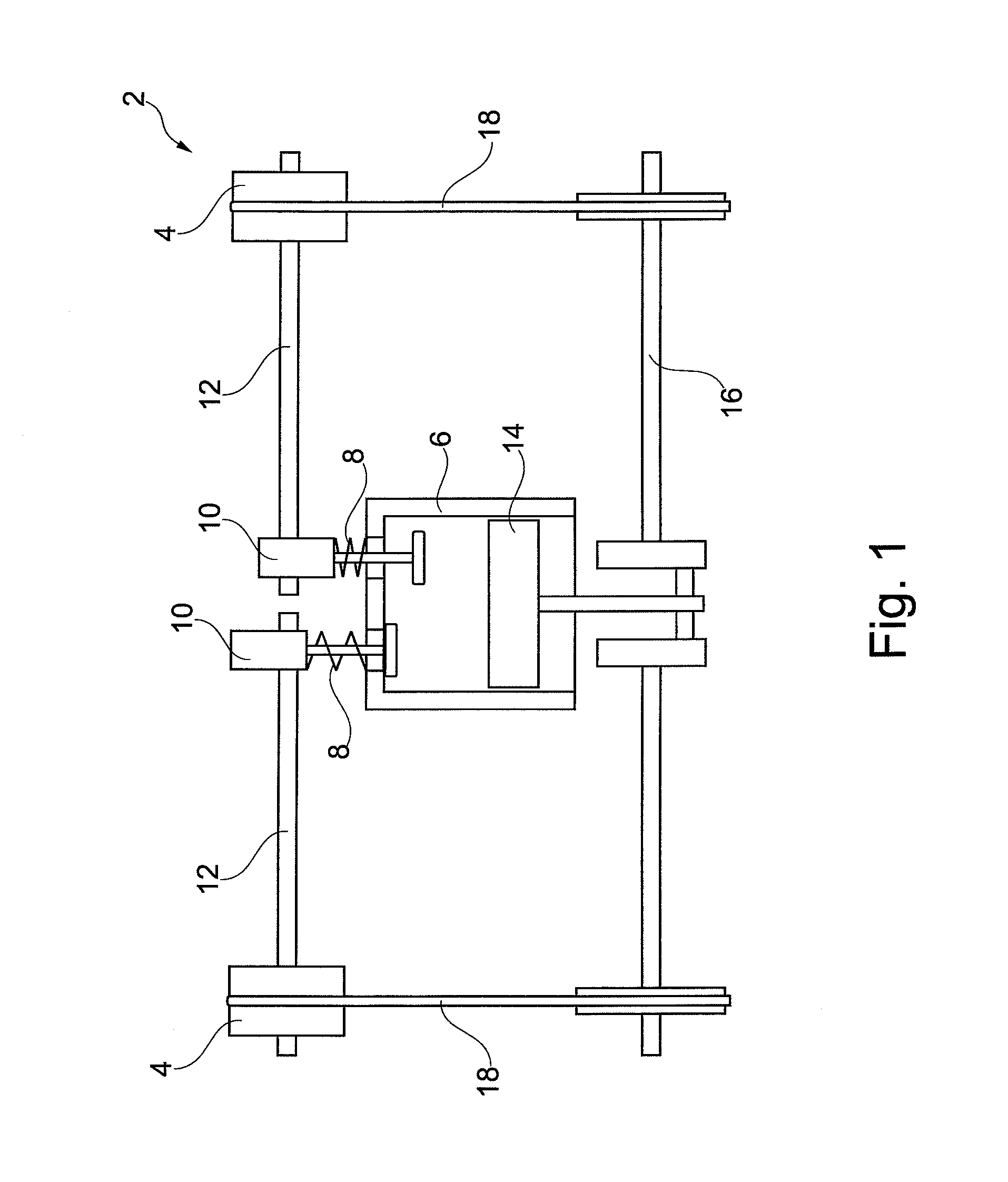
[0033]Reference is made to FIG. 1, which is a schematic illustration of an internal combustion engine 2 with camshaft adjusters 4.

[0034]The internal combustion engine 2 comprises, in a manner known per se, a combustion chamber 6 which can be opened and closed by valves 8. The valves are actuated by cams 10 on corresponding camshafts 12. In the combustion chamber 6 there is also accommodated a reciprocating piston 14 which drives a crankshaft 16. The rotational energy of the crankshaft 16 is transmitted, at the axial end thereof, via a drive element 18 to the camshaft adjuster 4. In the present example, the drive element may be a chain or a belt.

[0035]The camshaft adjusters 4 are mounted axially in each case on one of the camshafts 12, receive rotational energy from the drive element 18 and output rotational energy to the camshafts 12. Here, the camshaft adjusters 4 can...


PUM


Abstract

A directional valve (30) for controlling a hydraulic oil flow from a pressure port (34) via working chambers of a camshaft adjuster (4) to a tank port (58). The directional valve (30) includes an accumulator port (36) for conducting at least a part of the hydraulic oil flowing out of a working chamber into a volume accumulator (54) before said hydraulic oil flows out into the tank port (58), and the accumulator port (36) is connected via a passage (60) to the pressure port (34).

Description

INCORPORATION BY REFERENCE[0001]The following documents are incorporated herein by reference as if fully set forth: German Patent Application No. 102012201551.5, filed Feb. 2, 2012.FIELD OF THE INVENTION[0002]The invention relates to a directional valve for controlling a hydraulic oil flow from a pressure port via working chambers of a camshaft adjuster to a tank port, the camshaft adjuster, an internal combustion engine having the camshaft adjuster, a method for filling a volume accumulator in a camshaft adjuster, and a control device for carrying out the method.BACKGROUND OF THE INVENTION[0003]Camshaft adjusters are technical assemblies for adjusting the phase relationship between a crankshaft and a camshaft in an internal combustion engine.[0004]From WO 2011 032 805 A1, it is known to arrange a volume accumulator in a camshaft adjuster, wherein hydraulic liquid can be drawn from said volume accumulator by the pressure chambers in the event of a negative pressure.SUMMARY[0005]It i...

Claims


Application Information

Patent Timeline
IPC IPC(8): F01L1/344F16K15/00
CPCF01L1/3442F01L2001/34433F16K15/00F16K11/0716F01L1/344F01L2001/34446Y10T137/7837
Inventor SCHAFER, JENSSTEIGERWALD, MARTINBUSSE, MICHAELPLATE, JURGENRACKLEBE, STEFFENWEDEL, ANDREASBOESE, OLAFHEINEMANN, ROBERT
Owner SCHAEFFLER TECH AG & CO KG
Why Eureka
Try Eureka