Slewing bearing structure

a bearing structure and bearing technology, applied in the direction of roller bearings, mechanical equipment, rotary machine parts, etc., can solve the problems of adverse effects of bearing performance and other problems, and achieve the effects of suppressing contact angle shifting, reducing structural deformation, and avoiding sudden increase of contact pressur

Inactive Publication Date: 2013-08-08
MITSUBISHI HEAVY IND LTD
View PDF1 Cites 16 Cited by
  • Summary
  • Abstract
  • Description
  • Claims
  • Application Information

AI Technical Summary

Benefits of technology

[0025]A slewing bearing structure in accordance with a second aspect of the present invention is a slewing bearing structure of a rolling bearing in which a rolling element is put between bearing rings formed on an inner ring and an outer ring, wherein an initial contact angle, at which the rolling element contacts with a surface of the bearing rings under no load, is adapted to change in a circumferential direction so that a maximum contact pressure under weight load and structural deformation is decreased.
[0026]According to such slewing bearing structure, since the initial contact angle, at which the rolling element contacts with a surface of the bearing rings under no load, is adapted to change in a circumferential direction so that a maximum contact pressure under weight load and structural deformation is decreased, it is possible to avoid sudden increase of a contact pressure which happens when a contact angle is significantly shifted on receiving a load and a contact ellipse moves onto an edge portion. That is, since an initial contact angle, which used to be constant in a circumferential direction, is adapted to change in a circumferential direction so that the maximum contact pressure under weight load and structural deformation is decreased, the contact ellipse does not move onto an edge portion even under an operating load, and it is thus possible to suppress shifting of a contact angle to avoid sudden increase of the contact pressure.
[0027]A slewing bearing structure in accordance with a third aspect of the present invention is a slewing bearing structure of a rolling bearing in which a rolling element is put between bearing rings formed on an inner ring and an outer ring, wherein a groove radius of the bearing rings is adapted to change in a circumferential direction so that a maximum contact pressure under weight load and structural deformation is decreased.
[0028]According to such slewing bearing structure, since a groove radius of the bearing rings is adapted to change in a circumferential direction so that a maximum contact pressure under weight load and structural deformation is decreased, a contact pressure at a portion where the maximum contact pressure occurs can be suppressed while minimizing the increase in a bearing torque. That is, since the groove radius of the bearing rings, which used to be constant in a circumferential direction, is adapted to change in a circumferential direction so that the maximum contact pressure under weight load and structural deformation is decreased, a relation (or ratio) of a diameter of the rolling element and a groove radius of the bearing rings is optimized under operating load, enabling to suppress the maximum contact pressure and the bearing torque.
[0029]According to the above-described slewing bearing structures of the present invention, by adjusting and changing the rigidity of a bearing while minimizing the increase in weight, it is possible to prevent distortion of a pressure pattern caused by structural deformation from unfavorably affecting bearing performance to maintain favorable bearing performance.
[0030]Also, by altering and optimizing as needed an initial contact angle and a groove radius of a bearing ring in a circumferential direction, a sudden increase of a contact pressure can be avoided or a maximum contact pressure and a bearing torque can be suppressed.

Problems solved by technology

Thus, if the rigidity of the slewing bearing 10 is not enough, bearing performance also incurs adverse effects such as distortion of a pressure pattern caused by structural deformation of a surrounding area.

Method used


Image

  • Slewing bearing structure
  • Slewing bearing structure
  • Slewing bearing structure

Examples


first embodiment

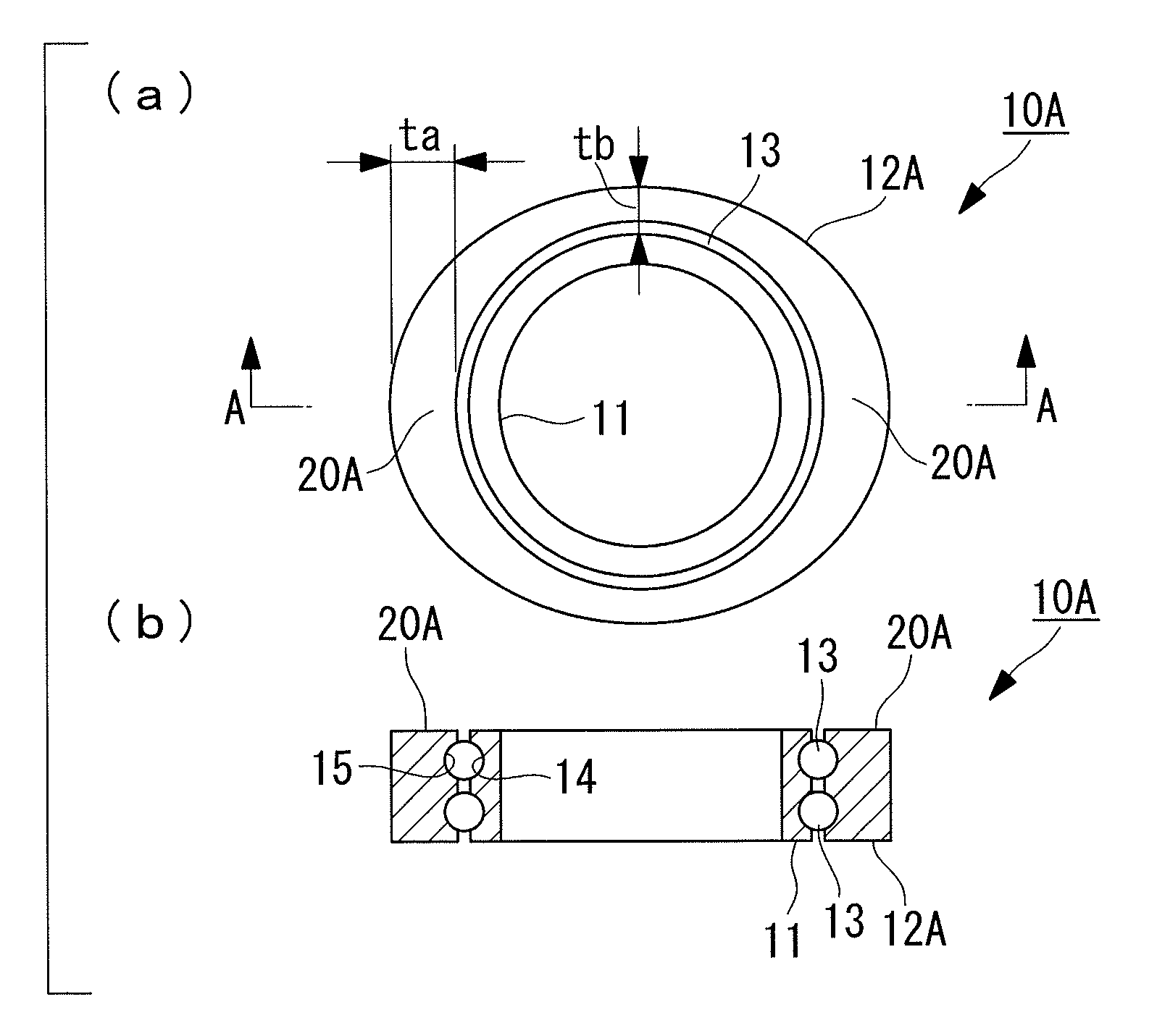
[0053]A slewing bearing 10A of an embodiment shown in FIG. 1 is a rolling bearing in which bearing rings 14 and 15 are formed on an inner ring 11 and an outer ring 12A, respectively, and rolling elements 13 are put between the confronting bearing rings 14 and 15. The illustrated slewing bearing 10A has a configuration in which two pairs of the bearing rings 14 and 15 are formed in a vertical direction and the rolling elements 13 are arranged in two levels, but the present invention is not limited to this configuration.

[0054]In the slewing bearing 10A of the present embodiment, a rigidity strengthening portion 20A, at which rigidity of the outer ring is increased more than at the peripheral portions, is formed at a circumferential area where a bearing contact pressure is high. A pattern of bearing contact pressures can be calculated in advance.

[0055]The illustrated rigidity strengthening portion 20A is a wide area created by altering an outer diameter of the outer ring 12A in out-of-...

second embodiment

[0075]A second embodiment of a clewing bearing structure in accordance with the present invention will now be described on the basis of FIGS. 8 to 11. FIGS. 8 and 9 are diagrams exaggerating a curvature of main elements or the like, and like numerals indicate like elements to skip detailed description.

[0076]FIG. 8 shows the spherical rolling element 13 put between the bearing ring 14 of the inner ring 11 and the bearing ring 15 of the outer ring 12 in a normal state in which a contact angle θ is in an appropriate state. In the normal state like this, an initial contact angle, which is 45 degrees from either horizontal or vertical axes, equals the contact angle θ, and four contact locations T are created. A radius of the rolling element 13 is indicated as r, and a curved surface of the bearing rings 14 and 15 is an arc of a radius R.

[0077]In the normal state shown in FIG. 8, a ball weight F is acting in a direction at the contact angle θ, which equals an initial contact angle of 45 d...

third embodiment

[0083]A third embodiment of a clewing bearing structure in accordance with the present invention will now be described on the basis of FIGS. 8, 12 and 13. FIG. 12 is a diagram exaggerating a curvature of main elements or the like, and like numerals indicate like elements to skip detailed description.

[0084]An inner bearing contact pressure of a plain bearing changes on the basis of a diameter of the rolling element 13 and a groove radius of the bearing rings 14 and 15, or a ratio of a radius r of the rolling element 13 and a groove radius R of an arc constituting the bearing rings 14 and 15 (a groove curvature=R / 2r). Specifically, if the groove curvature gets closer to 50% and a diameter 2r of the rolling element 13 and the groove radius R get closer to each other, a contact pressure becomes smaller.

[0085]But if the diameter of the rolling element 13 and the groove radius R get closer to each other, a contact area of the rolling element 13 increases, causing a bearing torque (a force...


PUM


Abstract

There is provided a slewing bearing structure capable of maintaining favorable bearing performance by adjusting and changing rigidity thereof while minimizing the increase in the weight thereof for preventing distortion of a pressure pattern caused by structural deformation from unfavorably affecting the bearing performance. A slewing bearing of a rolling bearing, in which a rolling element is put between bearing rings and formed on an inner ring and an outer ring, has a slewing bearing structure in which a rigidity strengthening portion, at which rigidity of the inner ring and/or the outer ring is increased more than that at peripheral portions, is formed at a circumferential area where a bearing contact pressure is high.

Description

BACKGROUND OF THE INVENTION[0001]1. Field of the Invention[0002]The present invention relates to a slewing bearing structure of a rolling bearing suitable for a yaw drive unit of a nacelle and a pitch drive unit of a wind turbine blade, for example.[0003]2. Description of the Related Art[0004]A wind turbine apparatus (hereinafter referred to as a wind turbine) 1 shown in FIG. 14 is an apparatus in which a rotor head 4 providing wind turbine blades 5 rotates by receiving wind and the speed of that rotation is increased by a gear box, for example, for driving a power generator to generate electricity.[0005]In the wind turbine apparatus 1, since the rotor head 4 providing the wind turbine blades 5 is connected via a main axis with the gear box and the power generator in a nacelle 3 provided at a top of a tower 2, the orientation of the rotor head 4 needs to be aligned with an ever-changing wind direction (or a rotor rotational plane needs to directly face against the wind direction).[0...

Claims


Application Information

Patent Timeline
Patent Type & Authority Applications(United States)
IPC IPC(8): F16C33/58F16C19/50
CPCF16C19/02F16C19/22F16C2360/31F16C19/522F16C2300/14F16C33/58
Inventor NODA, YOSHITOMONISHIURA, KENSUKENUMAJIRI, TOMOHIRO
Owner MITSUBISHI HEAVY IND LTD
Why Eureka
Try Eureka