
Torque Transmission Assembly, In Particular Hydrodynamic Torque Converter, Fluid Coupling Or Wet-Running Clutch

a transmission assembly and torque converter technology, applied in the direction of fluid gearings, shock absorbers, gearings, etc., can solve the problems of insufficient decoupling of vibrations, insufficient effect of speed-adaptive mass dampers in the low speed range, and insufficient decoupling effect of speed-adaptive mass dampers, etc., to achieve the effect of improving vibration damping characteristics and reducing the speed rang

Inactive Publication Date: 2013-08-15
ZF FRIEDRICHSHAFEN AG
View PDF5 Cites 38 Cited by
  • Summary
  • Abstract
  • Description
  • Claims
  • Application Information

AI Technical Summary

Benefits of technology

The present invention provides a torque transmission assembly, such as a hydrodynamic torque converter, fluid coupling, or wet clutch, that can improve vibration damping in the lower speed range. The invention includes one or more mass damper arrangements designed to tune to a predefined excitation frequency so that vibratory excitations occurring particularly in the range of lower rotational speeds can be eliminated more efficiently. The mass damper arrangement(s) can be located in the interior of the housing arrangement or coupled with the torsional vibration damper arrangement to improve tuning to determined excitation frequencies. The invention ensures sufficient installation space in the interior of the housing for providing a mass damper arrangement.

Problems solved by technology

It has been shown that a sufficient decoupling of vibrations cannot be ensured, particularly in the lower speed range, e.g., less than 1000 RPM, by torsional vibration damper arrangements of this kind which can also include two or more torsional vibration damper units working in series.
So-called speed-adaptive mass dampers are also not effectively decoupling to a sufficient degree in the lower speed range because of the comparatively low kinetic energy.
Therefore, speed-adaptive mass dampers are primarily characterized in that they have an amplitude reduction proportional to the rotational speed so that they can be tuned to a certain excitation order, but are nevertheless insufficiently effective in the low speed range.

Method used


Image

  • Torque Transmission Assembly, In Particular Hydrodynamic Torque Converter, Fluid Coupling Or Wet-Running Clutch
  • Torque Transmission Assembly, In Particular Hydrodynamic Torque Converter, Fluid Coupling Or Wet-Running Clutch
  • Torque Transmission Assembly, In Particular Hydrodynamic Torque Converter, Fluid Coupling Or Wet-Running Clutch

Examples


Embodiment Construction

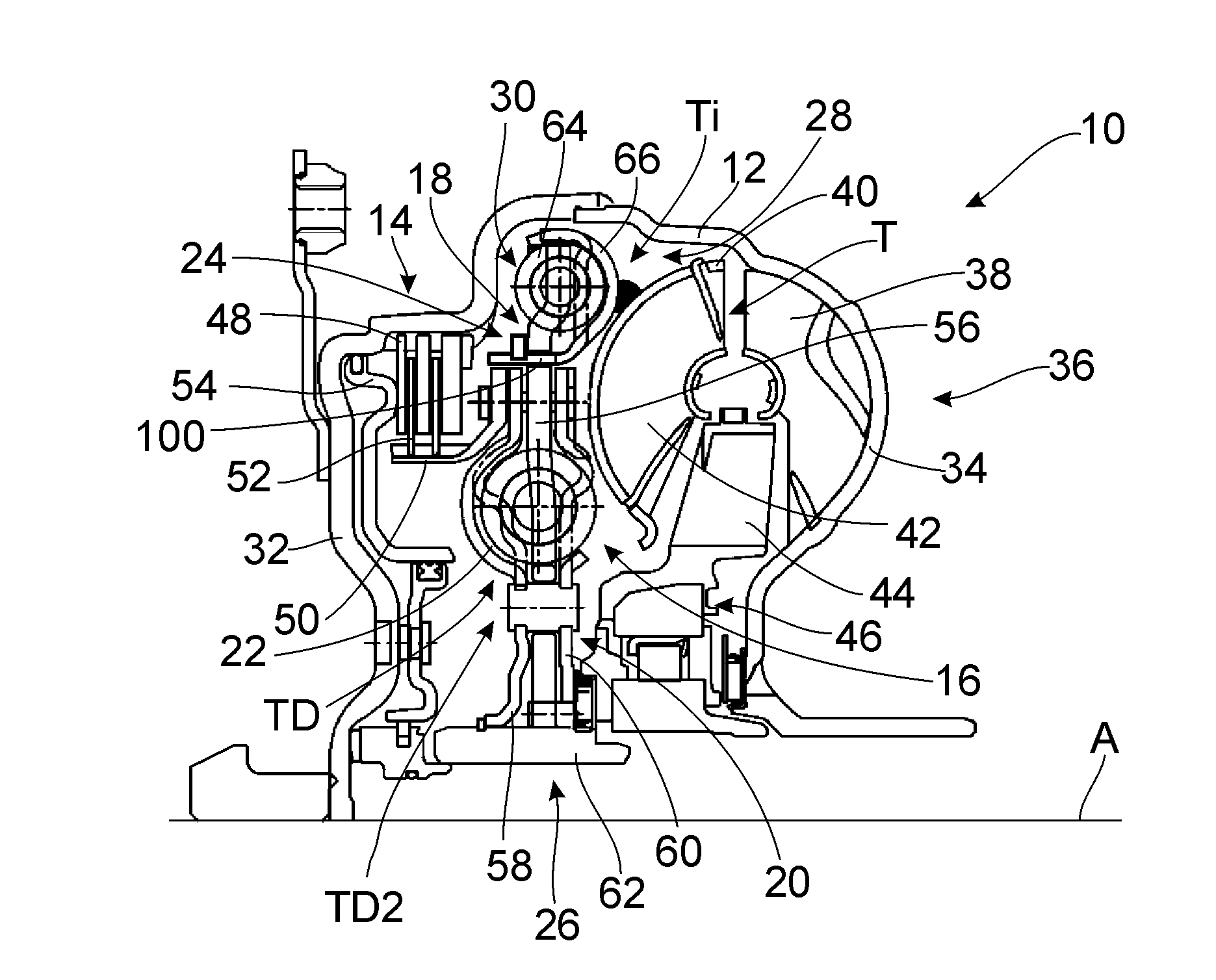
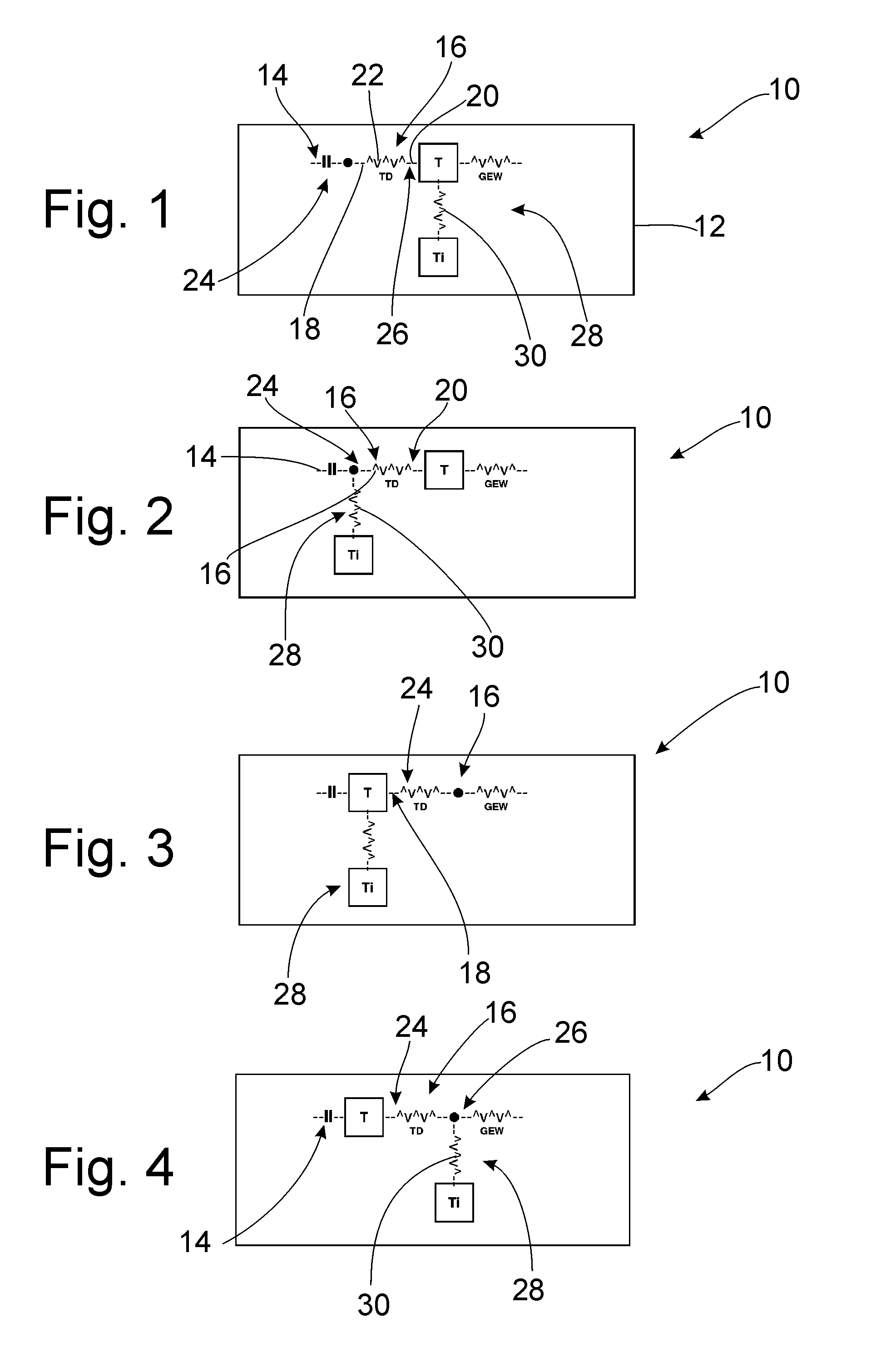
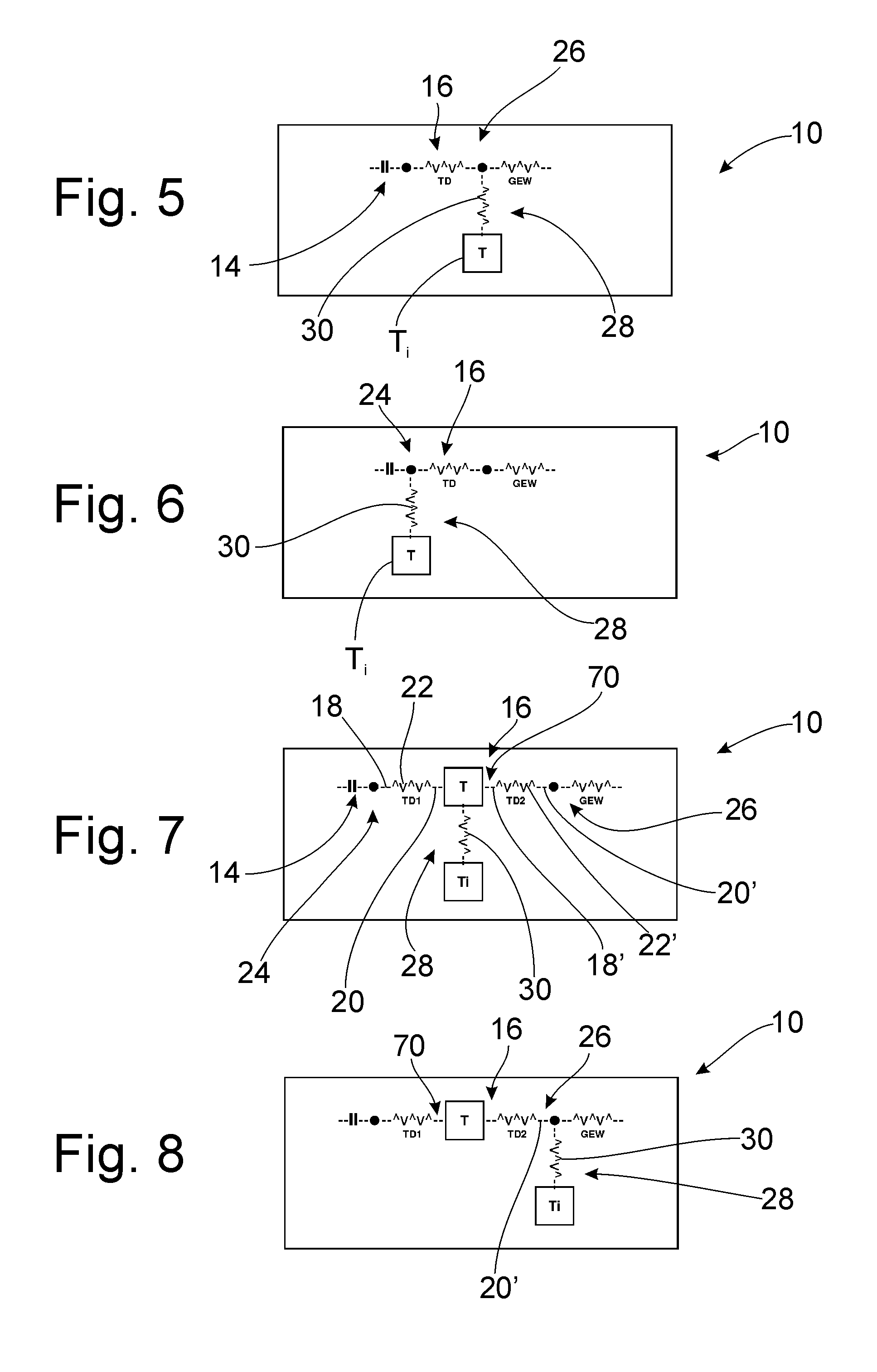
[0052]FIG. 1 is a schematic diagram showing a torque transmission assembly 10, e.g., in the form of a hydrodynamic torque converter. A turbine T is arranged in a housing 12, shown only schematically, into which a transmission input shaft GEW extends and which at the same time also provides or carries an impeller. This turbine T is coupled to the transmission input shaft GEW for transmission of torque. The turbine T and therefore the transmission input shaft GEW can be coupled directly, i.e., circumventing the fluid circuit, to the housing 12 via a lockup clutch 14 and a torsional vibration damper arrangement 16 in lockup mode.

[0053]In this construction, the torsional vibration damper arrangement 16 includes an individual torsional vibration damper unit TD with a primary side 18, a secondary side 20 and a damper spring arrangement 22 acting therebetween. In general this damper spring arrangement includes a plurality of damper springs, for example, helical compression springs, which a...


PUM


Abstract

A torque transmission assembly, particularly a hydrodynamic torque converter, a fluid coupling or a wet clutch, includes a housing arrangement that includes a torsional vibration damper arrangement having an input region which is coupled to or can be coupled to the housing arrangement and an output region to be coupled to a driven member. The torque transmission assembly also includes at least one mass damper arrangement having a damper mass arrangement which is coupled to the torque transmission assembly by a mass damper elastic arrangement.

Description

CROSS REFERENCE TO RELATED APPLICATIONS[0001]This is a U.S. national stage of application No. PCT / DE2011 / 055013, filed on 31 March 2011. Priority is claimed on German Application No. 10 2010 028735.0, filed 7 May 2010, the content of which is incorporated here by reference.BACKGROUND OF THE INVENTION[0002]1. Field of the Invention[0003]The present invention is directed to a torque transmission assembly which is constructed, for example, in the form of a hydrodynamic torque converter, a fluid coupling or a wet clutch.[0004]2. Description of the Prior Art[0005]Torque transmission assemblies of the type mentioned above are used in the drivetrain of vehicles to transmit torque between a drive unit, for example, an internal combustion engine, and a downstream region of a drivetrain, for example, a transmission. Various vibratory excitations occur in a drivetrain of this kind which can be triggered, for instance, by the ignition frequency of an internal combustion engine and which are thu...

Claims


Application Information

Patent Timeline
Patent Type & Authority Applications(United States)
IPC IPC(8): F16F7/10
CPCF16F15/1315F16F15/13484F16F15/1421F16F15/1442F16H45/02Y10T74/2122F16H2045/0226F16H2045/0231F16H2045/0247F16H2045/0284F16F7/1034F16H2045/021
Inventor SUDAU, JORGSTURMER, ARMINLOTZE, RUDIGERKRUGER, THOMASDROTT, CHRISTOPH
Owner ZF FRIEDRICHSHAFEN AG
Learn More