Method and system for the production of direct reduced iron using a synthesis gas with a high carbon monoxide content

a technology of synthesis gas and direct reduction iron, which is applied in the direction of manufacturing converters, furniture, lighting and heating apparatus, etc., can solve the problems of significantly increasing equipment costs and requiring a relatively large shift reactor, and achieves the effect of reducing equipment and catalyst costs, minimizing the size of the shift reactor used, and minimizing the amount of gas flow

Active Publication Date: 2013-08-15
MIDREX TECH INC
View PDF5 Cites 8 Cited by
  • Summary
  • Abstract
  • Description
  • Claims
  • Application Information

AI Technical Summary

Benefits of technology

[0006]In various exemplary embodiments, the present invention provides improved methods and systems for the production of DRI using coal gas or syn gas with a high CO content. The resulting reducing gas has a H2 / CO ratio of about 1.0 as it enters the DR furnace. Advantageously, the size of the shift reactor used is minimized, resulting in lower equipment and catalyst costs. This is achieved by minimizing the amount of gas flow that must be shifted to effect the desired H2 / CO ratio at the DR furnace.
[0007]Top gas or recirculated gas from the DR furnace is shifted, resulting in a lower flow to the shift reactor than is associated with existing methods and systems. This lower flow allows all of the above objectives to be achieved. Process analysis indicates that the volume of gas shifted using the top gas or recirculated gas may be only about 60-90% of the shifted gas flow when shifting the fresh syn gas, for example, depending upon the nitrogen content of the syn gas. This translates to a meaningful reduction in shift reactor size and cost, as well as catalyst volume and cost.

Problems solved by technology

Disadvantageously, all of the reducing gas has to flow through the shift reactor, requiring a relatively large shift reactor.
The high shift reactor temperatures required (about 800 degrees C.) also significantly increase equipment cost.

Method used


Image

  • Method and system for the production of direct reduced iron using a synthesis gas with a high carbon monoxide content
  • Method and system for the production of direct reduced iron using a synthesis gas with a high carbon monoxide content

Examples


Embodiment Construction

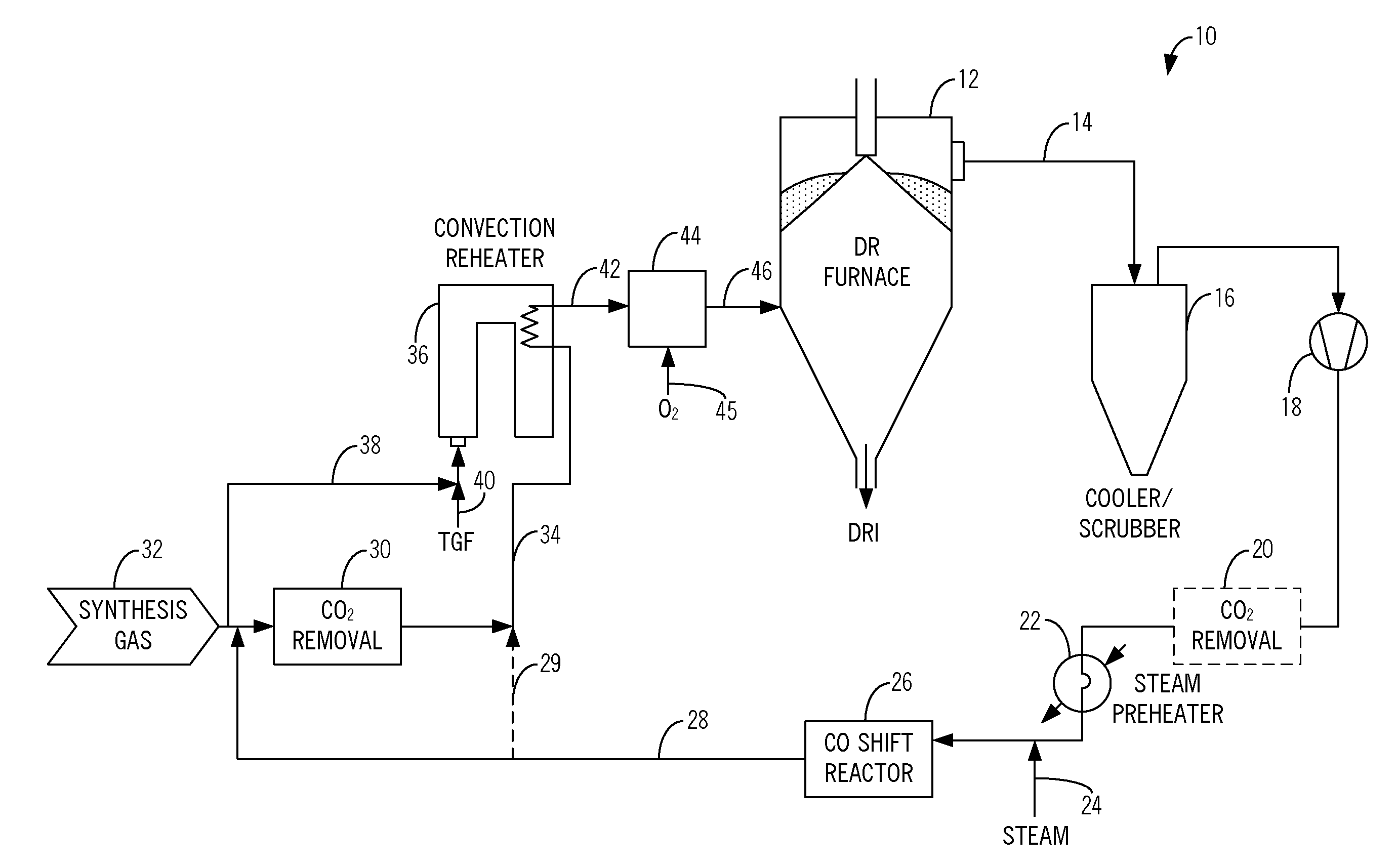
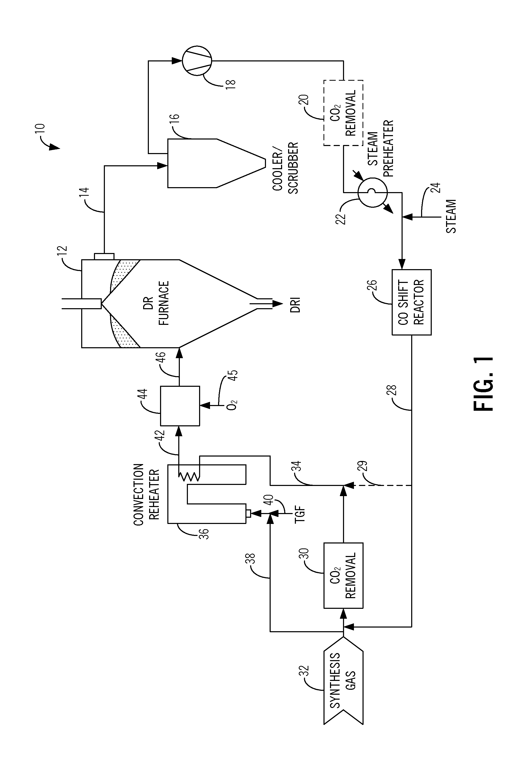
[0013]Referring to FIG. 1, in one exemplary embodiment of the present invention, the method and system 10 for the production of DRI using a coal gas or syn gas with a high CO content includes a DR furnace 12, such as a Midrex® DR shaft furnace or the like, well known to those of ordinary skill in the art, in which iron oxide pellets, lumps, and / or agglomerates are reduced using a countercurrent flow of reducing gas, consisting primarily of CO and H2. This reducing gas may be made from natural gas or other gaseous fuels, solid fuels, such as coal, liquid fuels, such as heavy fuel oil, or other export gases. The DRI descends as a moving packed bed through the DR furnace 12 by gravity. The DR furnace 12 has a converging discharge section through which the DRI is continually discharged.

[0014]Top gas 14 exits the DR furnace 12 near the top of the DR furnace 12 and is communicated to a cooler / scrubber 16 that cools and cleans the top gas, prior to compression by a compressor 18.

[0015]Opti...


PUM

PropertyMeasurementUnit
reduction temperatureaaaaaaaaaa
temperaturesaaaaaaaaaa
sizeaaaaaaaaaa

Abstract

Methods and systems for the production of direct reduced iron, including: removing a top gas from a direct reduction furnace; carbon monoxide shifting the top gas using a carbon monoxide shift reactor to form a carbon monoxide shifted top gas having a reduced carbon monoxide content; adding one of a coal gas, a synthesis gas, and an export gas to at least a portion of the carbon monoxide shifted top gas to form a combined gas; removing carbon dioxide from the combined gas using a carbon dioxide removal unit to form a carbon dioxide lean combined gas; and providing the carbon dioxide lean combined gas to the direct reduction furnace as a reducing gas for producing direct reduced iron after heating to reduction temperature. Optionally, the method includes removing carbon dioxide from the top gas using a carbon dioxide removal unit prior to carbon monoxide shifting the top gas.

Description

FIELD OF THE INVENTION[0001]The present invention relates generally to methods and systems for the production of direct reduced iron (DRI). More specifically, the present invention relates to methods and systems for the production of DRI using a synthesis (syn) gas with a high carbon monoxide (CO) content.BACKGROUND OF THE INVENTION[0002]Syn gas generated from coal gasification processes or the like contains large amounts of CO, moderate amounts of hydrogen (H2), plus oxidants, such as water vapor (H2O) and carbon dioxide (CO2). The oxidant levels may vary, depending upon the processes used to generate the syn gas. For example, if a melter-gasifier is used to generate the syn gas, whereby molten iron is produced as a product or by-product, an intermediate product of the pre-reduced iron is made using the melter gases and fed back to the melter, and off gases from the pre-reduction unit are exported for further use, the CO2 content may be quite high (>25%). This syn gas may have a...

Claims


Application Information

Patent Timeline
Patent Type & Authority Applications(United States)
IPC IPC(8): C21B3/04F27D99/00F27B17/00
CPCC21B13/0073C21B13/004C21B2100/24C21B2100/282Y02P10/122Y02P10/134
Inventor MEISSNER, DAVID C.METIUS, GARY E.HUGHES, GREGORY D.
Owner MIDREX TECH INC
Why Eureka
Try Eureka