Athermal radiation type oil burner and a method for reducing greenhouse gas emissions

Inactive Publication Date: 2013-08-15
NG KING CHING
View PDF23 Cites 0 Cited by
  • Summary
  • Abstract
  • Description
  • Claims
  • Application Information

AI Technical Summary

Benefits of technology

[0005]For eliminating the inadequacies of the existing burner, a purpose of the present invention is to provide an athermal radiation type oil burner comprising: a furnace body in which a hearth is placed; the hearth composed of a casing with multiple through holes includes a primary oil supply combustion chamber, a secondary oil supply combustion chamber and an obstruction chamber; the primary oil supply combustion chamber is a casing divided into an upper layer and a lower layer, between which is arranged an interconnect hole; multiple through holes are distributed on the casing and communicated wi

Problems solved by technology

The main greenhouse gas is carbon dioxide; with the concentration of carbon dioxide in the atmosphere rising to a dangerous level, massive latent natural disasters have appeared gradually.
But it ultimately failed to reach a unanimous agreement mainly for the following reasons: There is not yet a good effective method to solve the greenhouse gases of the present climate.
Thus, the industrial develop

Method used


Image

  • Athermal radiation type oil burner and a method for reducing greenhouse gas emissions
  • Athermal radiation type oil burner and a method for reducing greenhouse gas emissions

Examples


Embodiment Construction

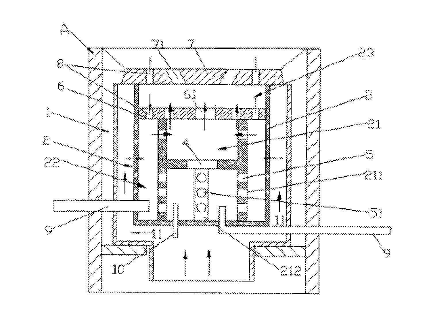
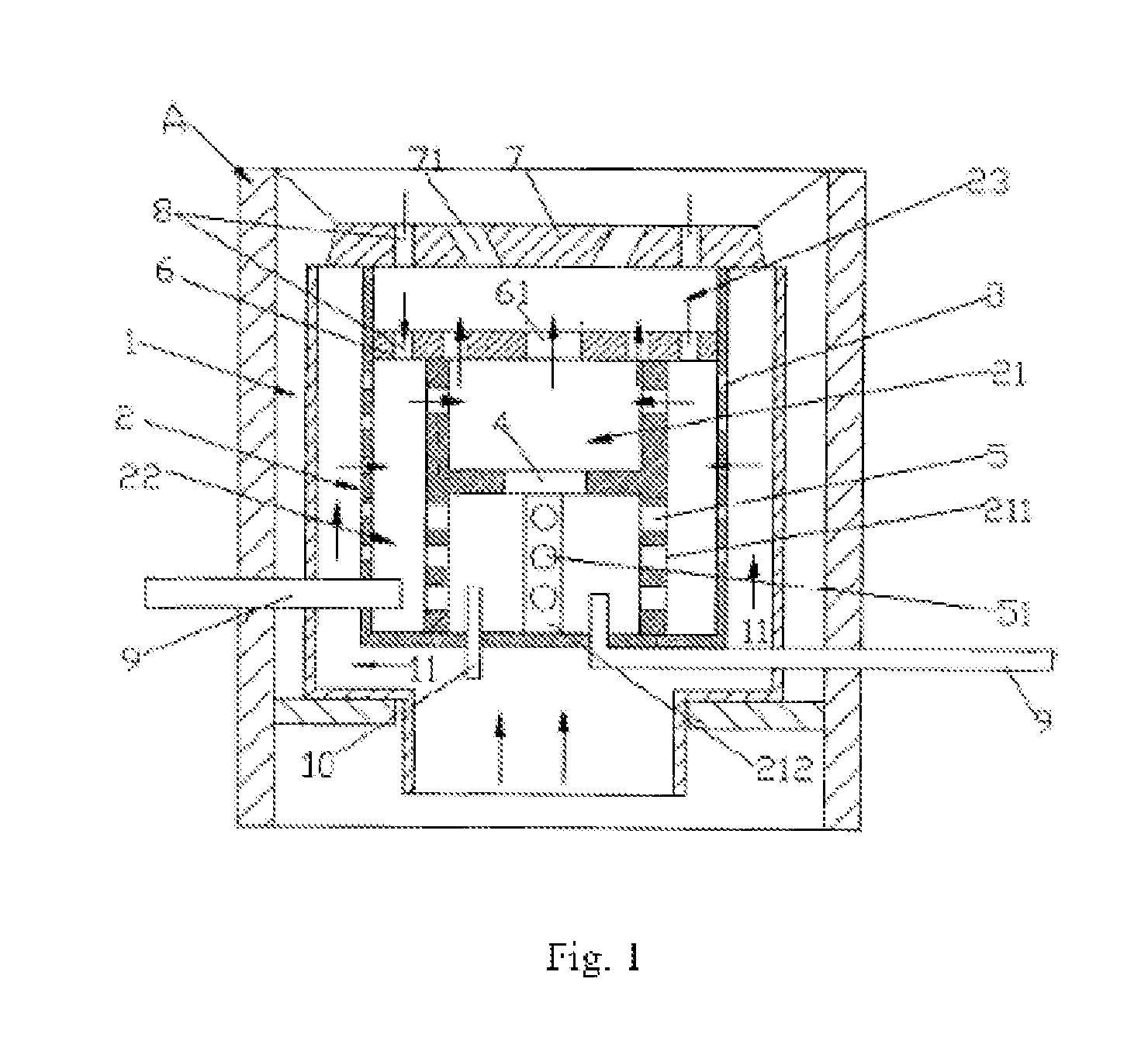
[0018]A method of the present invention for reducing greenhouse gas (CO2) emissions is to install an athermal radiation type oil burner on a stove A.

[0019]The athermal radiation type oil burner, as shown in FIG. 1, includes: a furnace body 1 in which a hearth 2 is placed; an air chute 11 is arranged between the furnace body 1 and the hearth 2; the hearth 2 composed of a casing with multiple through holes 3 includes a primary oil supply combustion chamber 21, a secondary oil supply combustion chamber 22 and an obstruction chamber 23; the hearth 2 is provided inside with two oil ports 9 that are respectively connected to a connecting tube, one connecting tube being connected to a lower end of the primary oil supply combustion chamber 21, the other connecting tube being connected to a lower end of the secondary oil supply combustion chamber 22; the primary oil supply combustion chamber 21 is a casing 211 divided into an upper layer and a lower layer, between which is arranged an interc...


PUM


Abstract

Disclosed is an oil combustion method for reducing greenhouse gas emissions in which an athermal radiation type oil burner is arranged on a stove. The athermal radiation type oil burner includes a furnace body (1) in which a hearth (2) is placed. The hearth (2) composed of a casing with multiple through holes (3) includes a primary oil supply combustion chamber (21), a secondary oil supply combustion chamber (22) and an obstruction chamber (23). The primary oil supply combustion chamber (21) is a casing (211) divided into an upper layer and a lower layer. An interconnected hole (4) is arranged between the two layers. Multiple through holes (5) are distributed on the casing (211) and communicated with the secondary oil supply combustion chamber (22), which is formed by the interval among the casing (211) of the primary oil supply combustion chamber (21), an isolation plats (6) with multiple through holes (61) arranged on the casing (211) and the hearth (2). The obstruction chamber (23) is composed of a sealing plate (7) on the furnace body (1) and the isolation plate (6). Flame holes (71) are arranged on the sealing plate (7). Air flow holes (8) are formed on the corresponding positions of the isolation plate (6) and sealing plate (7), respectively. The secondary oil supply combustion chamber (22) and the obstruction chamber (23) are interconnected with the air flow holes (8). Oil in the burner is continuously spilt, gasified, expanded and compressed for multiple times in the furnace body (1), and oil molecules completely release heat energy and do not release heat radiation again. The burner ensures that generated harmful gas is reduced.

Description

FIELD OF THE INVENTION[0001]The present invention relates to a combustion device, particularly to a combustion device with oil as the fuel and a method for reducing, greenhouse gas emissions using the same.BACKGROUND OF PRIOR ART[0002]The atmosphere is filled of various gaseous compounds and compound particles, which include a variety of greenhouse gases defined as contributing to global warming by the “United Nations Framework Convention on Climate Change”, such as nitrogen dioxide, nitrogen oxide, carbon monoxide, carbon dioxide and sulfur dioxide. These greenhouse gases are caused mainly by the economic development and daily life behavior of the human being, for example, as caused by such industrial developments as aircrafts, ships, cars, power plants, factories and food industry, and as caused by such everyday life activities as cook, electricity consumption and waste production. The majority of energy used in industrial production and daily life is provided by fossil fuels (coa...

Claims


Application Information

Patent Timeline
IPC IPC(8): F24C5/12
CPCF24C5/12F23D5/04
Inventor NG, KING CHING
Owner NG KING CHING
Why Eureka
Try Eureka