Laser apparatus and laser materials processing apparatus provided with same

a laser material and laser technology, applied in the direction of laser beam welding apparatus, lasers, manufacturing tools, etc., can solve the problems of large optical loss and limited fiber transmission distance, and achieve the effect of reducing the amount of spattering matter, improving the quality of the processed surface, and easy mutually independent

Active Publication Date: 2013-08-22
NIPPON STEEL CORP
View PDF5 Cites 18 Cited by
  • Summary
  • Abstract
  • Description
  • Claims
  • Application Information

AI Technical Summary

Benefits of technology

[0032]In the laser apparatus described in the above (a), the first laser beam is emitted from the core of the passive fiber, and the second laser beam is emitted from the inner cladding of the passive fiber. When processing is performed while a laser beam is moved, an overlapping component between the second laser beam and the first laser beam is irradiated to a part to be processed after the second laser beam is irradiated to the part to be processed.
[0033]That is, processing of the workpiece is performed by a laser beam with sufficient energy for processing after a member to be processed is preheated by the second laser beam. In this case, although the energy absorption of the laser beam occurs in the preheated location, in the laser apparatus described in the above (a), the power density of the second laser beam is made smaller than the power density of the overlapping component between the first laser beam and the second laser beam. For this reason, this energy absorption does not occur excessively. As a result, even if the processing speed is low or the workpiece is thick, the quality of a processed surface is improved and the amount of spattering matter can be reduced.
[0034]Additionally, in the laser materials processing apparatus described in the above (e), the second laser beam having energy suitable for preheating the workpiece, and the overlapping component between the second laser beam and the first laser beam, which has sufficient energy to process the workpiece, are coaxially emitted. Since these laser beams are emitted from different light sources, the energy of these laser beams can be easily and mutually independently set to values suitable for respective processing. As a result, even if the processing speed is low or the workpiece is thick, the roughness of a processed surface becomes small and the amount of spattering can be reduced. Therefore, the quality of the part to be processed can be improved.

Problems solved by technology

The single mode output in these region causes, the large optical loss due to nonlinear effects such as stimulated Brillouin scattering or Raman scattering within the core of the optical fiber.
Therefore, the distance by which fiber transmission is allowed is limited to about several meters.

Method used


Image

  • Laser apparatus and laser materials processing apparatus provided with same
  • Laser apparatus and laser materials processing apparatus provided with same
  • Laser apparatus and laser materials processing apparatus provided with same

Examples


example 1

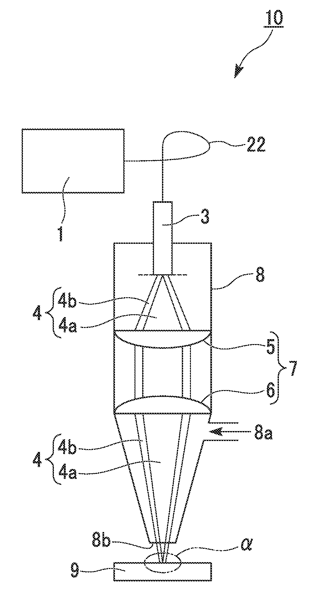
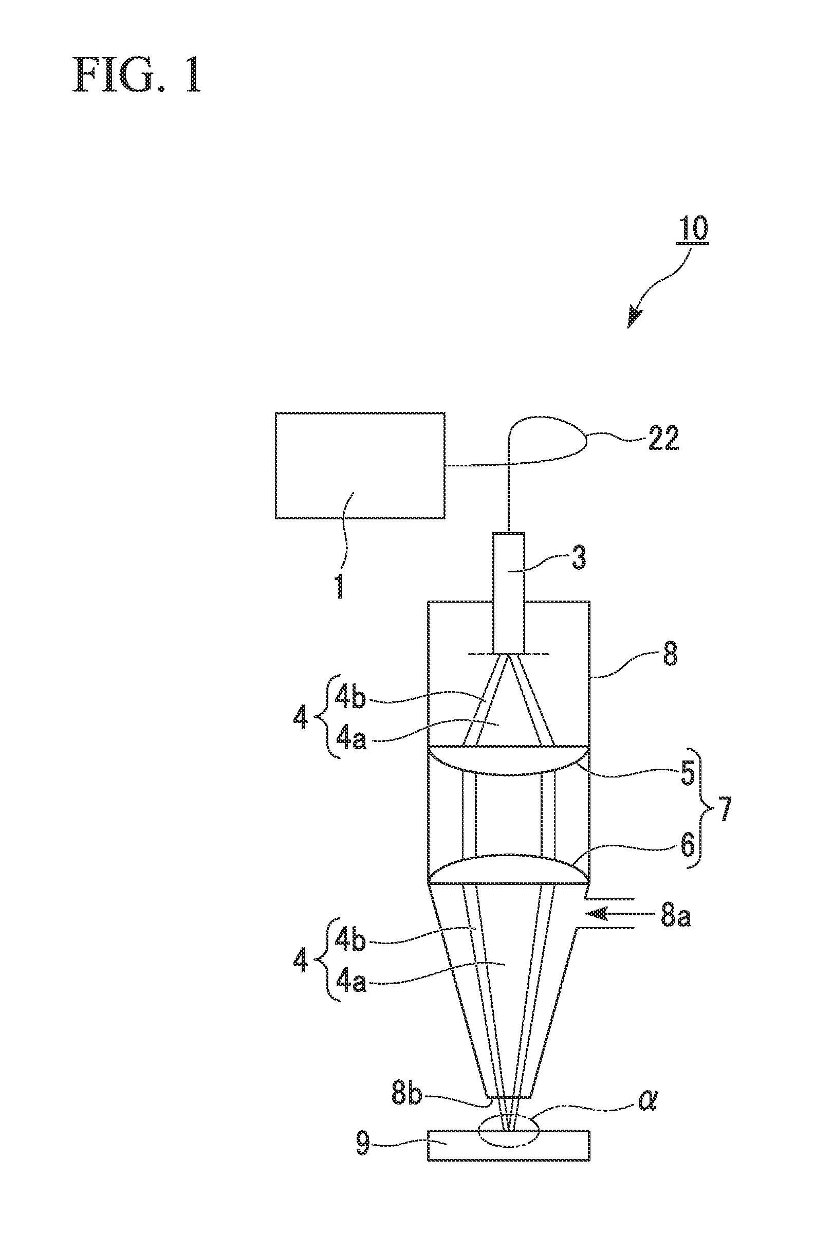
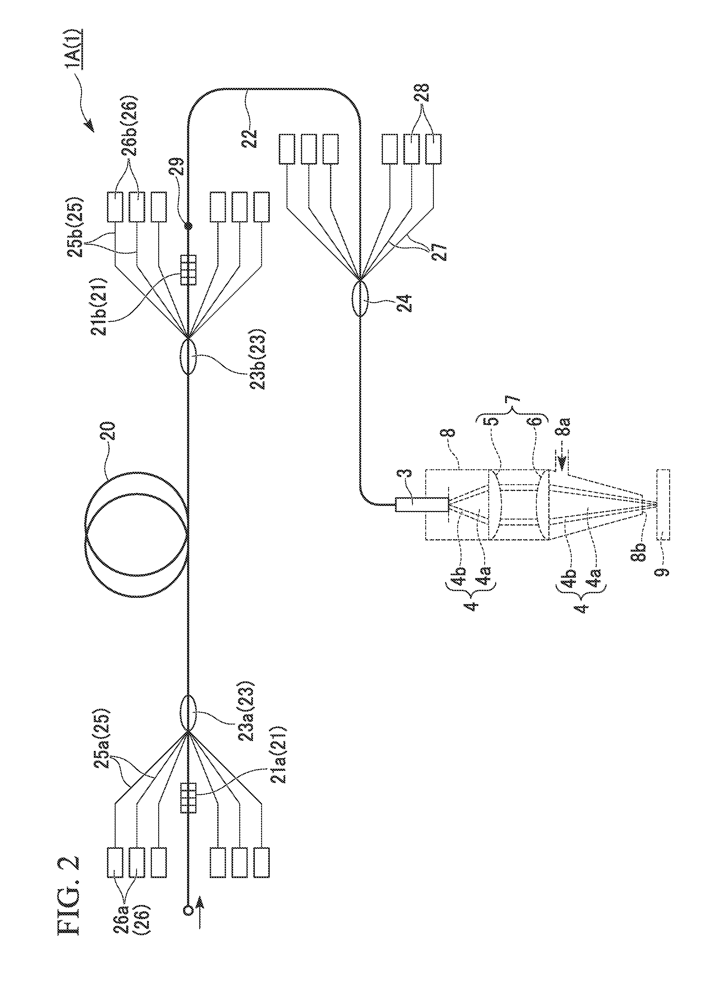
[0099]As Example 1 of the present invention, the laser apparatus 1A shown in FIG. 2 was assembled, and the laser materials processing apparatus 10 shown in FIG. 1 was assembled using this laser apparatus.

[0100]The wavelength of signal light was 1085 nm, and the wavelength of pumping light and a semiconductor laser beam was 976 nm.

[0101]As the active fiber, a double cladding fiber in which the core diameter is 0.2 mm, the diameter of the inner cladding is 0.8 mm, and Yb that is doped on the core was used.

[0102]As the passive fiber, a double-clad fiber in which the core diameter is 0.2 mm, the diameter of the inner cladding is 0.8 mm, without a rare earth element doping to the core, was used. The relative index difference between the core and the inner cladding was 0.002.

[0103]The maximum output obtained from the output end of the laser apparatus 1A was 4 kW in the fiber laser beam with a wavelength of 1085 nm and was 2 kW in the semiconductor laser beam with a wavelength of 976 nm. I...

example 2

[0111]The plate thickness of SUS304 was changed and cut in a range of 1 to 12 mm, using the same laser materials processing apparatus as the above-described Example 1 and comparative example.

[0112]With respect to respective plate thicknesses, first, a cutting speed that minimizes the cutting surface roughness Rz at P2=0 was obtained (comparative example). As the plate thickness became larger, the cutting speed decreased. Next, P2 was now changed at the obtained cutting speed, and P2 where a minimum cutting surface roughness Rz is obtained was determined (Example 2). In addition, the respective values of P2 in Example 2 satisfy the above Formula (7).

[0113]The results are shown in Table 2 and FIG. 11.

TABLE 2Example 2Comparative ExamplePlatePlateThicknessVP2RzThicknessVP2Rz(mm)(mpm)(W)(μm)(mm)(mpm)(W)(μm)115180017.3115018.627150019.527022.343130022.043026.962120026.862035.481.4110027.881.4044.1101100031.6101053.6120.780033.4120.7060.7

[0114]In the comparative example (P2=0), the cutting...

example 3

[0115]Overlapping welding of 2 mm-thick steel sheets was performed using the same laser materials processing apparatus 10 as the above-described Example 1 and comparative example. In this case, the overlapping welding was performed while changing the welding speed as shown in Table 3. The welding length is 100 mm. The mass of the steel before and after welding was measured and the amount of reduction in the mass was evaluated. The results are shown in Table 3 and FIG. 12. In Example 3, the value of P2 when the amount of reduction in the mass becomes the minimum is obtained. Then, the value of P2 and the value of reduction in the mass are recorded. In addition, the respective values of P2 in Example 3 satisfy the above Formula (7).

TABLE 3Example 3Comparative ExampleMassMassVP2ReductionVP2Reduction(mpm)(W)(g)(mpm)(W)(g)0.78000.360.700.69110000.35100.65212000.31200.53313000.25300.37413500.25400.29514000.23500.25

[0116]In the comparative example, as the welding speed was slow, the amount...


PUM

PropertyMeasurementUnit
wavelengthaaaaaaaaaa
thicknessaaaaaaaaaa
surface roughnessaaaaaaaaaa

Abstract

A laser apparatus of the present invention has a first laser oscillator that emits a first laser beam; a passive fiber that is a double-clad fiber that transmits the first laser beam through a core; and a second laser oscillator that emits a second laser beam that is coupled into inner cladding of the passive fiber. Additionally, a laser materials processing apparatus of the present invention is provided with the laser apparatus; and an irradiation optical system having a collimating lens and a condenser lens.

Description

TECHNICAL FIELD[0001]The present invention relates to a laser apparatus to be used when a metallic material or the like is processed, and a laser materials processing apparatus provided with this laser apparatus.BACKGROUND ART[0002]In recent years, in a field of materials processing with high-power lasers, attention is paid to processing by a laser apparatus using an optical fiber to which rare earth elements are doped. The laser emits a wavelength of 1 μm band, and an optical-fiber delivery is possible unlike CO2 laser used in the related art. Additionally, since this laser can be focused to a smaller spot than CO2 laser, it is suitable for high-speed processing or fine micro processing, such as cutting, welding, or the like. Regarding this laser apparatus, there are already a number of well-known techniques (for example, refer to Patent Document 1).[0003]An example of a laser materials processing apparatus 100 of the related art is schematically shown in FIG. 13. The laser materia...

Claims


Application Information

Patent Timeline
Patent Type & Authority Applications(United States)
IPC IPC(8): H01S3/067
CPCB23K26/0613H01S3/06716H01S3/0675H01S3/005H01S3/09408H01S3/175H01S3/23H01S3/094011
Inventor IMAI, HIROFUMIHIRANO, KOJI
Owner NIPPON STEEL CORP
Why Eureka
Try Eureka