Secondary-battery monitoring device and battery pack

a monitoring device and battery pack technology, applied in electrochemical generators, safety/protection circuits, instruments, etc., can solve the problems of high risk of swelling, heat generation, ignition, etc., and achieve the effects of reducing variations in an overcurrent determination curren

Active Publication Date: 2013-09-05
MITSUMI ELECTRIC CO LTD
View PDF16 Cites 27 Cited by
  • Summary
  • Abstract
  • Description
  • Claims
  • Application Information

AI Technical Summary

Benefits of technology

[0016]In a secondary-battery monitoring device according to an embodiment, when an overcurrent flowing to a secondary battery is to be detected by utilizing a current detection voltage generated via on-resistance of charge-control and discharge-control FETs, a correction voltage having a characteristic that is varied by positive slope or negative slope approximating an slope of the detection voltage reduced along with increase in a power supply voltage is generated, and the correction voltage is added to the detection voltage or a reference power supply voltage with a polarity that cancels out the slope of voltage variation caused in the detection voltage and then input to a comparator circuit. As a result, input to the comparator circuit is corrected by the correction voltage, thereby reducing variations in an overcurrent determination current.
[0017]In a secondary-battery monitoring device according to an embodiment, when an overcurrent flowing to a secondary battery is to be detected by utilizing a current detection voltage generated via on-resistance of charge-control and discharge-control FETs, a correction voltage having a characteristic approximated by a linear function or a quadratic function to a characteristic of the detection voltage varied depending on a power supply voltage is generated, and the correction voltage is added to the detection voltage or a reference power supply voltage with a polarity that cancels out the slope of voltage variation caused in the detection voltage and then input to a comparator circuit. As a result, input to the comparator circuit is corrected by the correction voltage, thereby reducing variations in an overcurrent determination current.
[0018]Furthermore, in a secondary-battery monitoring device according to another embodiment, when an overcurrent flowing to a secondary battery is to be detected by utilizing a current detection voltage generated via on-resistance of charge-control and discharge-control FETs, the device includes means that generates a correction voltage having a characteristic that is increased by positive slope along with increase in a power supply voltage and means that generates a corrected detection voltage by adding the correction voltage to the detection voltage, a reference power supply voltage is applied to one side of a comparator circuit, and the corrected detection voltage is applied to the other side of the comparator circuit. As a result, input to the comparator circuit is corrected by the correction voltage, thereby reducing variations in an overcurrent determination current.

Problems solved by technology

However, due to the high capacity, the lithium-ion secondary battery has high risks of swelling, heat generation, and ignition in a state of, for example, overcharging and short-circuit between external connection terminals.

Method used


Image

  • Secondary-battery monitoring device and battery pack
  • Secondary-battery monitoring device and battery pack
  • Secondary-battery monitoring device and battery pack

Examples


first embodiment

[0068]>

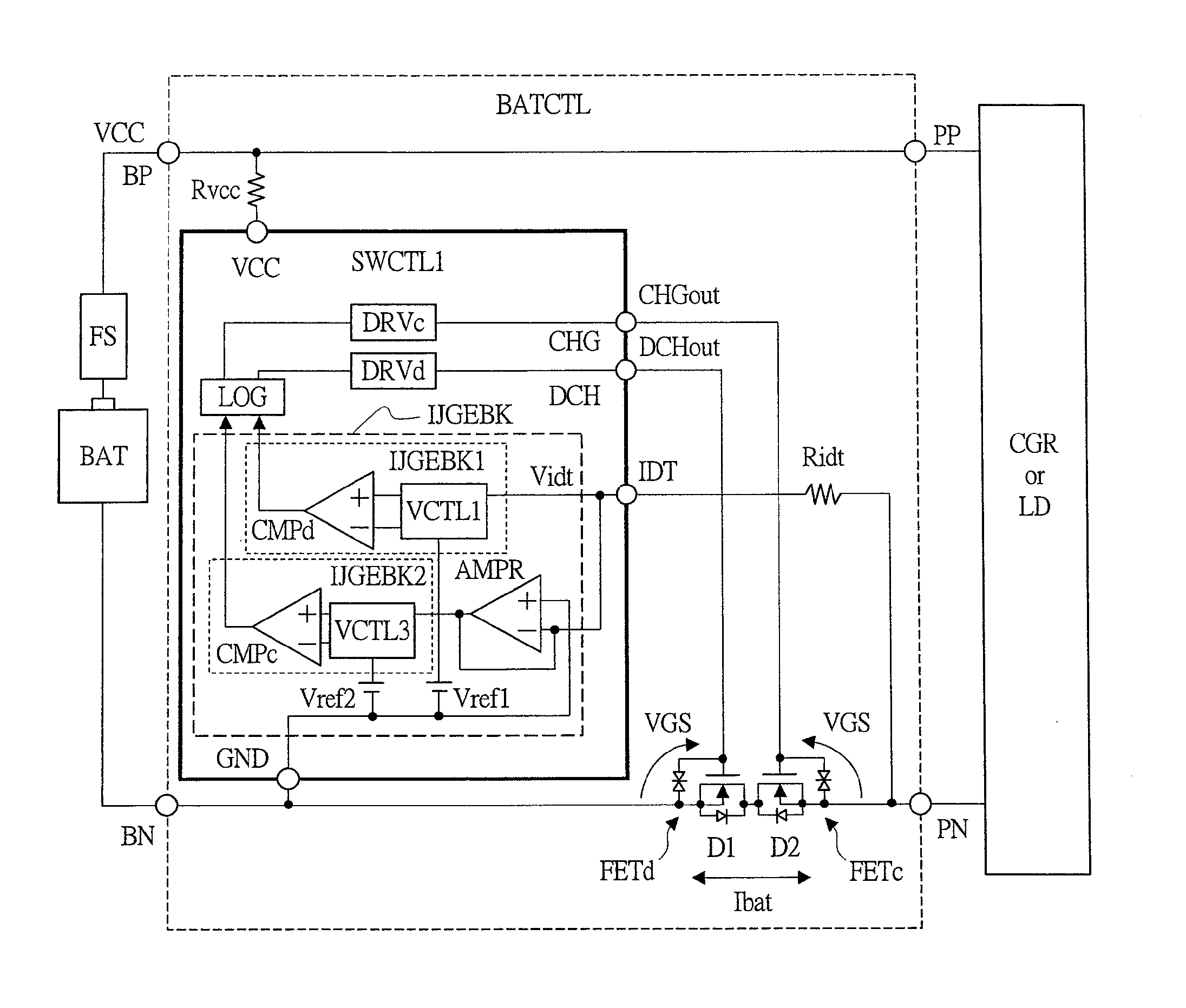
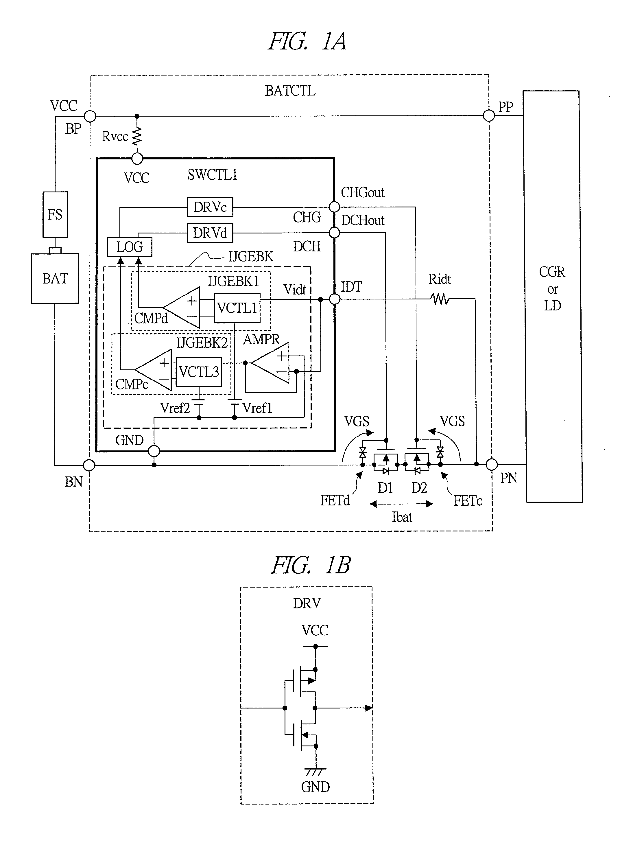
[0069]FIG. 1A is a schematic drawing showing a configuration example of a main part of a battery pack according to a first embodiment of the present invention. The battery pack shown in FIG. 1 is provided with a secondary battery (battery) BAT, a fuse FS, and a secondary-battery monitoring device BATCTL which controls charging and discharging of BAT. BAT is typically a lithium-ion secondary battery. When a large current flows to BAT, the fuse FS shuts off the current path thereof to protect BAT. BATCTL is provided with a positive terminal BP and a negative terminal BN for connecting BAT and also a positive terminal PP and a negative terminal PN for connecting a charger CGR which charges BAT or a load circuit LD which is driven by BAT. A power supply voltage VCC from BAT is supplied to BP and a ground power supply voltage GND from BAT is supplied to BN. When CGR or LD is connected between PP and PN, current paths are respectively formed between BP and PP and between BN and PN....

second embodiment

[0096]>

[0097]FIG. 7 is a circuit diagram showing a detailed configuration example of a voltage correction circuit of a secondary-battery monitoring device according to a second embodiment of the present invention. FIG. 8A to FIG. 8C are explanatory drawings showing operation examples of the voltage correction circuit of FIG. 7. The voltage correction circuit VCTL1a shown in FIG. 7 has a configuration example in which the straight-line approximation (first-order approximation) of FIG. 3 is applied to the voltage correction circuit VCTL1 of FIG. 2A described above. VCTL1a is provided with the resistors R1 and R2 which carry out resistor voltage division between the power supply voltage VCC and the ground power supply voltage GND, the resistors R3 and R4 which carry out resistor voltage division between the resistor voltage dividing node thereof and the negative node (−) of the comparator circuit CMPd, and an amplifier circuit AMP1.

[0098]At the amplifier circuit AMP1, an overcurrent de...

third embodiment

[0103]>

[0104]FIGS. 9A and 9B are schematic drawings showing configuration examples of a main part of a battery pack according to a third embodiment of the present invention. The battery pack shown in FIGS. 9A and 9B is different from the battery pack of FIG. 1 in a point that a power-supply-voltage generating circuit VGEN is added into the switch control unit SWCTL2. Since the configuration other than this is similar to that of the case of FIG. 1, detailed description thereof will be omitted. The power-supply-voltage generating circuit VGEN receives the power supply voltage VCC from the secondary battery (battery) BAT and steps down VCC to generate a power supply voltage VDD. The power-supply-voltage generating circuit VGEN which generates VDD can be typically composed of a Zener diode or a step-down regulator circuit. VDD thereof is supplied to the driver circuits DRVc and DRVd as a power supply voltage.

[0105]FIG. 10A to FIG. 10D are explanatory drawings showing schematic operation...


PUM


Abstract

A secondary-battery monitoring device capable of realizing highly reliable overcurrent detection and a battery pack having it are provided. When an overcurrent flowing to a secondary battery is to be detected by utilizing a current detection voltage generated via on-resistance of a discharge-control switch and a charge-control switch, a voltage correction circuit that generates a correction voltage having a characteristic varied by positive slope or negative slope along with increase in a power supply voltage is provided, and the correction voltage is added to the detection voltage or a reference power supply voltage with the polarity that cancels out the slope of voltage variation caused in the detection voltage, and then the voltage is input to a comparator circuit. In this manner, variation in the overcurrent determination current is reduced.

Description

CROSS-REFERENCE TO RELATED APPLICATION[0001]The present application claims priority from Japanese Patent Application No. 2012-046043 filed on Mar. 2, 2012, the content of which is hereby incorporated by reference into this application.TECHNICAL FIELD OF THE INVENTION[0002]The present invention relates to a secondary-battery monitoring device and a battery pack, and relates to techniques effectively applied to, for example, a secondary-battery monitoring device for monitoring a lithium-ion secondary battery and to a battery pack including the secondary-battery monitoring device and the lithium-ion secondary battery.BACKGROUND OF THE INVENTION[0003]For example, Japanese Patent Application Laid-Open Publication No. 2002-374630 (Patent Document 1), Japanese Patent Application Laid-Open Publication No. 2009-131020 (Patent Document 2), Japanese Patent Application Laid-Open Publication No. 2001-14042 (Patent Document 3) and Japanese Patent Application Laid-Open Publication No. H11-127543 (...

Claims


Application Information

Patent Timeline
Patent Type & Authority Applications(United States)
IPC IPC(8): H02J7/00
CPCH02J2007/0039H02J7/0072H02J7/00304Y02E60/10H02J7/00302H02J7/00308H02J7/00714H02J7/007182H02J7/00306H02H7/18H01M10/48G01R31/374G01R31/392G01R31/3842G01R19/12G01R19/0038G01R19/16566G01R19/1659G01R15/04H02J7/005G01R19/16542H01M10/4257H02J7/00H02J7/00036
Inventor NAGATA, SHOGOSO, YASUAKIYAMAGUCHI, TAKESHIKAWAGUCHI, NORIHITO
Owner MITSUMI ELECTRIC CO LTD
Why Eureka
Try Eureka