Protein or peptide printing method, protein array or peptide array and functional protein or functional peptide identification method
a printing method and protein technology, applied in the field of protein or peptide printing method, can solve the problems of protein and other biomolecules being susceptible to denaturation and decomposition, and achieve the effects of low storage stability, high density, and high usage valu
- Summary
- Abstract
- Description
- Claims
- Application Information
AI Technical Summary
Benefits of technology
Problems solved by technology
Method used
Image
Examples
first embodiment
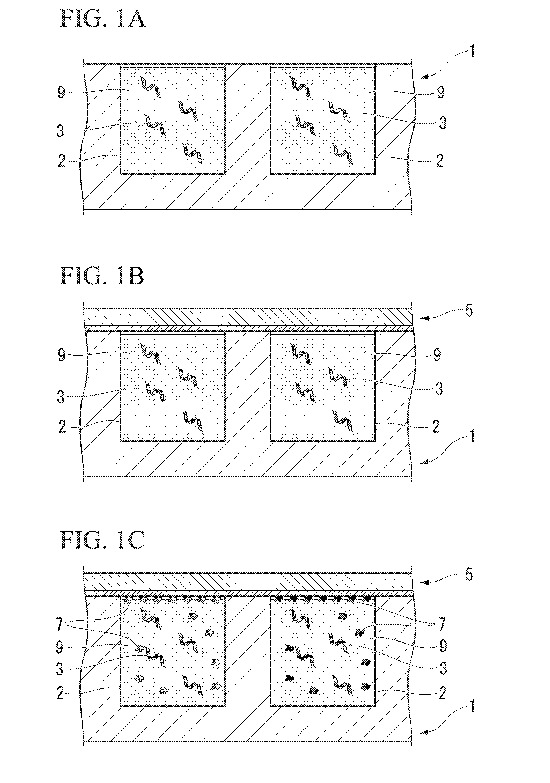
[0046]As shown in FIGS. 1A to 1C, the protein or peptide printing method of the present embodiment comprises:
[0047](a) a step for preparing nucleic acids 3 and an acellular protein synthesis system (a cell-free protein synthesis system) 9 in an engraved plate (a microintaglio plate) 1 composed of microscopic grooves 2 having a specific opening shape,
[0048](b) a step for superimposing a substrate 5 on the engraved plate 1 so as to contact a protein or peptide 7 to be synthesized in the microscopic grooves 2, and
[0049](c) a step for synthesizing the protein or peptide 7 from the nucleic acids 3 using the acellular protein synthesis system 9 in the microscopic grooves 2, and immobilizing the protein or peptide 7 on the substrate 5 along the specific opening shapes of the microscopic grooves 2.
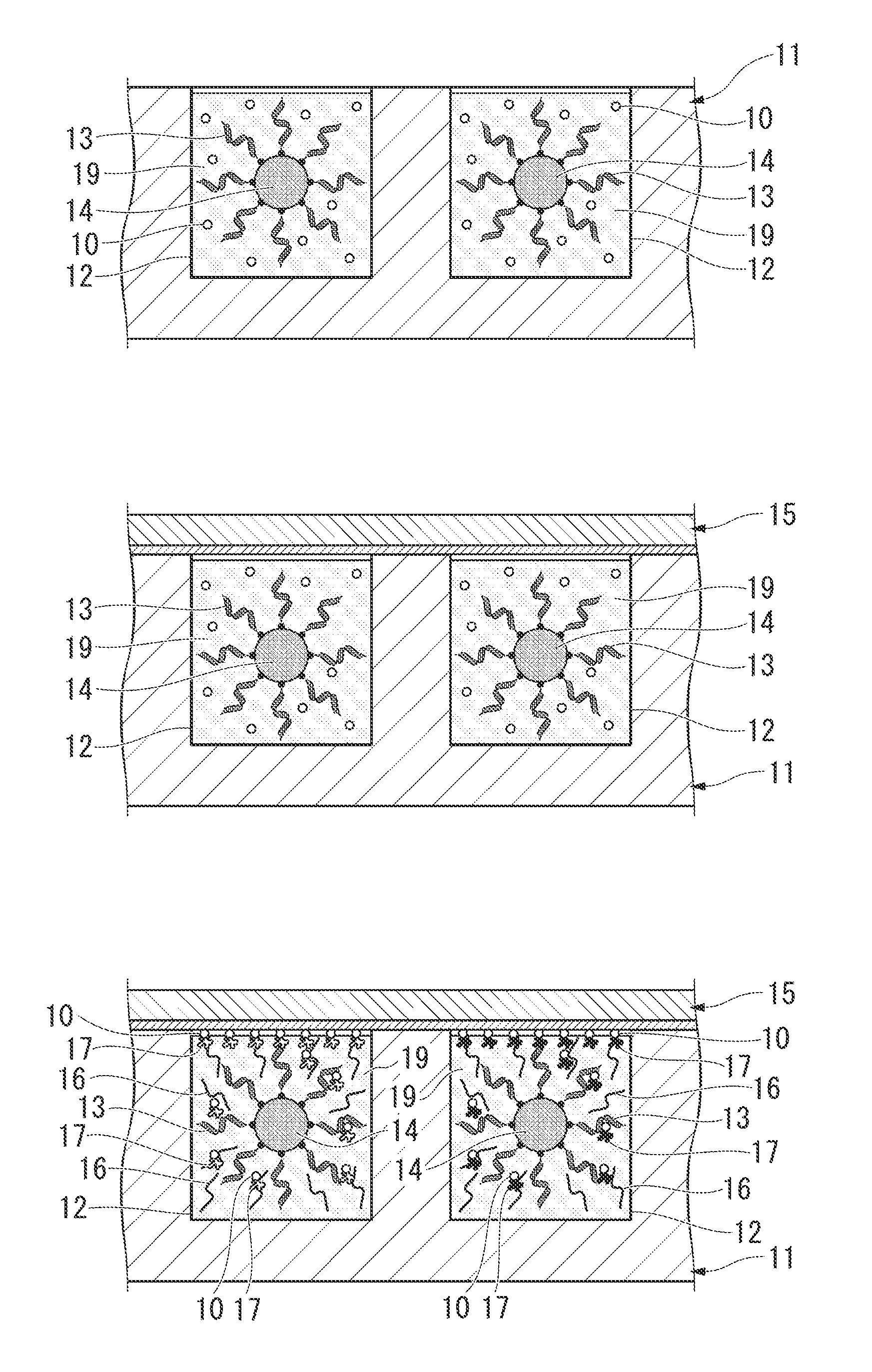
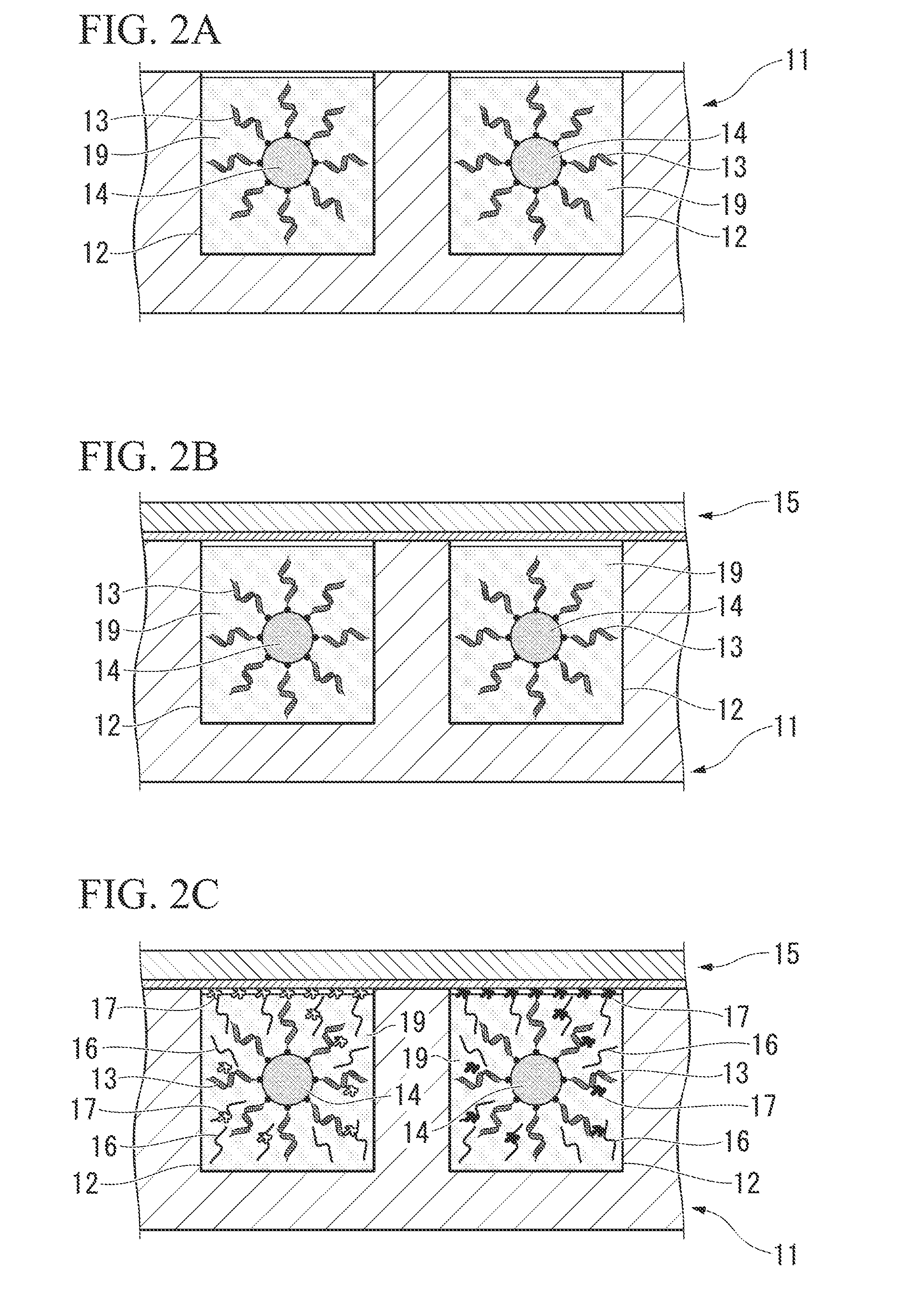
[0050]The following provides an explanation of each step with reference to FIGS. 2A to 2E.
[0051]Step (a) is a step for preparing nucleic acids and an acellular protein synthesis system 19 in the m...
second embodiment
[0091]As shown in FIGS. 3A to 3C, the protein or peptide printing method of the present embodiment comprises:
[0092](a) a step for preparing the nucleic acids 3, a biotinylated puromycin derivative 10 and the acellular protein synthesis system 9 in the engraved plate 1 composed of the microscopic grooves 2 having a specific opening shape,
[0093](b) a step for superimposing the avidin-labeled substrate 5 on the engraved plate 1 so as to contact the protein or peptide 7 to be synthesized in the microscopic grooves 2, and
[0094](c) a step for synthesizing the protein or peptide 7 from the nucleic acids 3 using the acellular protein synthesis system 9 in the microscopic grooves 2, and immobilizing the protein or peptide 7 on the substrate 5 along the specific opening shapes of the microscopic grooves 2.
[0095]The following provides an explanation of each step with reference to FIGS. 4A to 4E. In FIGS. 4A to 4E, the same reference symbols are used to indicate those constituent features in FI...
examples
Fabrication of cDNA-Bound Magnetic Beads
[0118]30 μl of streptavidin-labeled beads having a diameter of about 40 μm (approx. 300 beads) were transferred to a 1.5 ml tube, and the beads were attracted to the bottom of the tube using a magnet followed by removal of the supernatant. After washing twice using 1× binding buffer (10 mM Tris-HCl (pH 8.0), 1 mM EDTA, 1 M NaCl and 0.1% Triton X-100), 50 μl of Green Fluorescent Protein (GFP)-His-tagged cDNA labeled with biotin (40 pmol) and 50 μl of 2× binding buffer (20 mM Tris-HCl (pH 8.0), 2 mM EDTA, 2 M NaCl and 0.2% Triton X-100) were added followed by mixing by inverting for 60 minutes. After attracting the beads to the bottom of the tube using a magnet and removing the supernatant, the beads were suspended in 10 μl of PBS or TNT (trade name) reaction buffer (Promega Corp.).
[0119](Introduction of cDNA-Bound Magnetic Beads into Intaglio Plate)
[0120]10 μl of the cDNA-bound magnetic bead suspension fabricated in the manner described above w...
PUM
| Property | Measurement | Unit |
|---|---|---|
| Affinity | aaaaa | aaaaa |
Abstract
Description
Claims
Application Information
 - R&D
- Intellectual Property
- Life Sciences
- Materials
- Tech Scout
- Unparalleled Data Quality
- Higher Quality Content
- 60% Fewer Hallucinations
Browse by: Latest US Patents, China's latest patents, Technical Efficacy Thesaurus, Application Domain, Technology Topic, Popular Technical Reports.
© 2025 PatSnap. All rights reserved.Legal|Privacy policy|Modern Slavery Act Transparency Statement|Sitemap|About US| Contact US: help@patsnap.com


