Optical coherence tomography using spectrally controlled interferometry

a coherence tomography and optical coherence technology, applied in the field of optical coherence tomography using spectrally controlled interferometry, can solve the problems of inconvenient operation, inconvenient use, and inability to meet the specific application that is best addressed, and achieve the effect of reducing the coherence length of the fringes and improving the accuracy of measurements

Active Publication Date: 2013-09-19
OLSZAK ARTUR G
View PDF8 Cites 11 Cited by
  • Summary
  • Abstract
  • Description
  • Claims
  • Application Information

AI Technical Summary

Benefits of technology

[0013]According to one aspect of the invention, the spectral distribution is tuned sinusoidally to produce a modulation peak at a value of OPD equal to the optical path length difference between the object and reference arms of a Fizeau interferometer, thereby making it possible to use the Fizeau configuration to carry out white-light measurements without the coherence noise typical of laser interferometers. The common-axis configuration of the Fizeau interferometer affords all the advantages of white-light interferometry (measurement by scanning through the height of the sample surface; relative immunity from spurious fringes) together with the simpler construction of laser interferometry.
[0014]According to another aspect of the invention, unwanted interference from reflections on interfaces in the optical path toward the measured object (such as from the surfaces of a glass plate overlaying the sample surface, for instance) can be removed by illuminating the object with a light source with the appropriate spectral characteristics. Namely, the power spectrum of the light source is tuned to produce a peak with a time delay τ corresponding only to the OPD between the reference arm and the position of the sample surface of interest along the optical path of the object arm. By manipulating the spectral density of the light source, the coherence length of the fringes is also decreased to avoid interference produced by reflections from the other surfaces.
[0015]Another application of the invention is the implementation of OPD scanning (such as in conventional WLI scanning) without the use of mechanical means. The effect of OPD scanning is replicated with a sp

Problems solved by technology

In particular, interferometric methods rely on the interference of two beams of light to produce interference patterns from which measurement information about a test surface can be extracted.
Each type of interferometer has strengths over the other, but also weaknesses that render it unsuitable for particular applications that are best addressed by the other.
However, they are susceptible to coherence noise, such as speckle and diffraction patterns caused by contamination, because high-coherence lig

Method used


Image

  • Optical coherence tomography using spectrally controlled interferometry
  • Optical coherence tomography using spectrally controlled interferometry
  • Optical coherence tomography using spectrally controlled interferometry

Examples


example

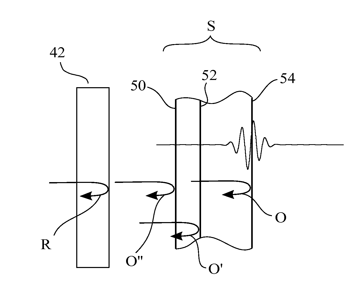
[0035]Referring to FIG. 5, assume that it is desired to produce modulation fringes with a peak at a distance l=2 mm from the reference surface 42 of a Fizeau interferometer. It is also desired to produce fringes with a modulation envelope E having full-width half-maximum (FWHM) visibility over a range w=10 μm along the direction of propagation and further with a period p=250 nm between interference fringes. Mathematically, the fringe envelope is described by the equation

I(τ)=δ(τ-τ0)⊗exp(-τ2τw2),(7)

where δ is the Dirac delta function, and is the convolution operator. In the time domain, fringes with a peak at a distance l=2 mm from the reference surface will

result from an object beam delay of

τ=2lc=1.33·10-11sec

with respect to the reference beam. Similarly, the time corresponding to the FWHM visibility range Σw and to the fringe period τp will be given by

τw=2wcandτp=2pc,

respectively. Note that the same fringe distribution is produced also for zero and negative values of the time dela...


PUM


Abstract

The time delay (and therefore the OPD) between object and reference beams in an interferometer is manipulated by changing the spectral properties of the source. The spectral distribution is tuned to produce a modulation peak at a value of OPD equal to the optical distance between the object and reference arms of a Fizeau interferometer, thereby enabling the use of its common-axis configuration to carry out white-light measurements free of coherence noise. Unwanted interferences from other reflections in the optical path are also removed by illuminating the object with appropriate spectral characteristics. OPD scanning is implemented without mechanical means by altering the source spectrum over time so as to shift the peak location by a predetermined scanning step between acquisition frames. The invention and its advantages are applicable to optical coherence tomography as well as conventional white light interferometry.

Description

RELATED APPLICATIONS[0001]This application is a continuation-in-part application of U.S. Ser. No. 12 / 816,091, filed Jun. 15, 2010, which was based on and claimed the benefit of priority of U.S. Provisional Application No. 61 / 187,024, filed Jun. 15, 2009, both of which are hereby incorporated by reference in their entirety.BACKGROUND OF THE INVENTION[0002]1. Field of the Invention[0003]This invention relates in general to the field of interferometry and, in particular, to a novel interferometric methods and interferometers for simultaneously obtaining the advantages of both white light and high coherence interferometry by modulating the spectral distribution of the light source.[0004]2. Description of the Prior Art[0005]High-accuracy shape measurements are an indispensable part of modern technology. In particular, interferometric methods rely on the interference of two beams of light to produce interference patterns from which measurement information about a test surface can be extra...

Claims


Application Information

Patent Timeline
IPC IPC(8): G01B9/02
CPCG01B9/02025G01B9/02002G01B9/0209G01B9/02057
Inventor OLSZAK, ARTUR G.
Owner OLSZAK ARTUR G
Why Eureka
Try Eureka