
Integrated hydroprocessing and fluid catalytic cracking for processing of a crude oil

a technology of which is applied in the field of integrated hydroprocessing and fluid catalytic cracking process, can solve the problems of incomplete catalyst conversion, affecting the efficiency of hydroprocessing, so as to reduce the correlation index of the bureau of mines, reduce the content of contaminants, and increase paraffinity

Active Publication Date: 2013-09-26
SAUDI ARABIAN OIL CO
View PDF6 Cites 14 Cited by
  • Summary
  • Abstract
  • Description
  • Claims
  • Application Information

AI Technical Summary

Benefits of technology

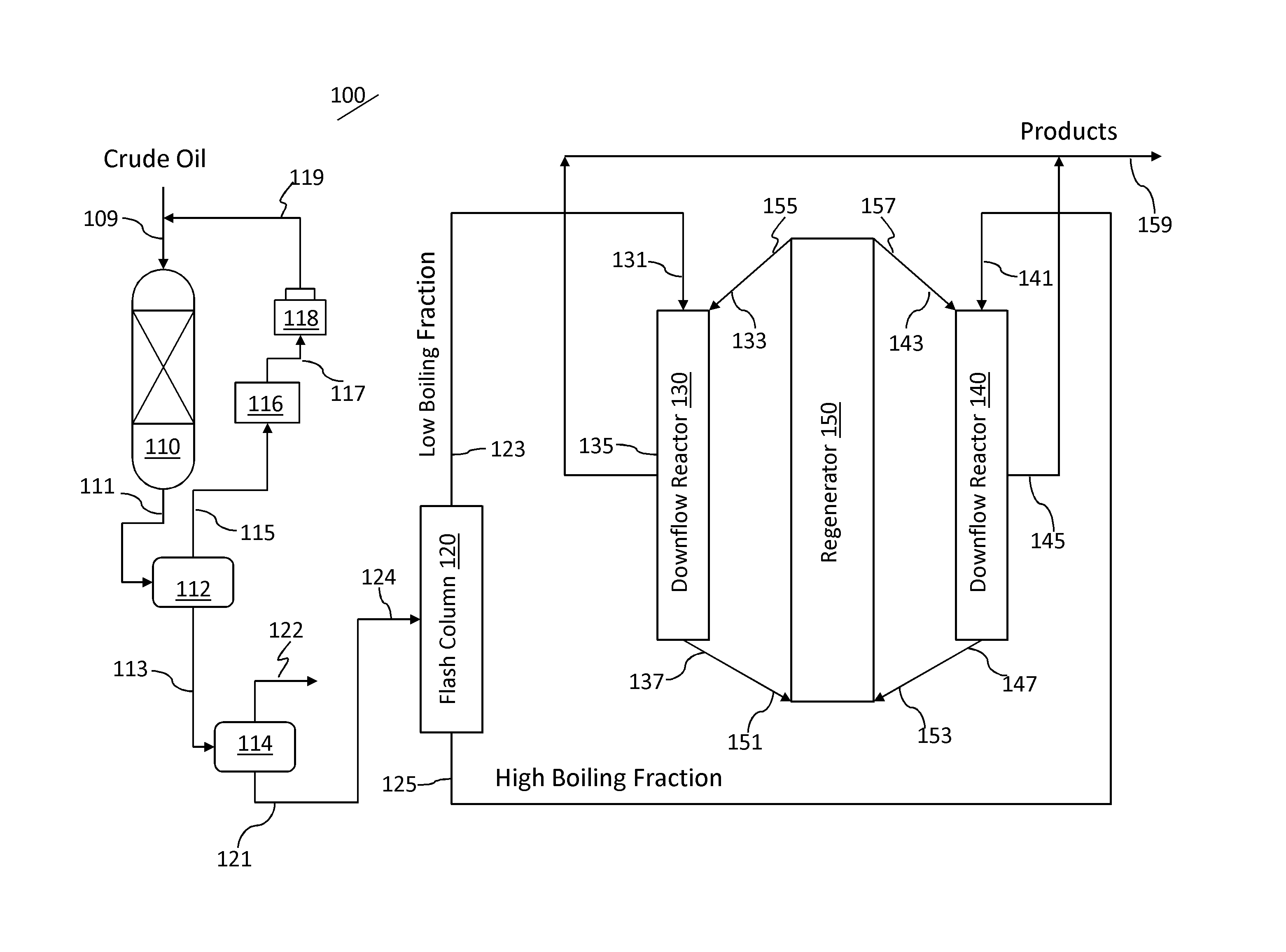
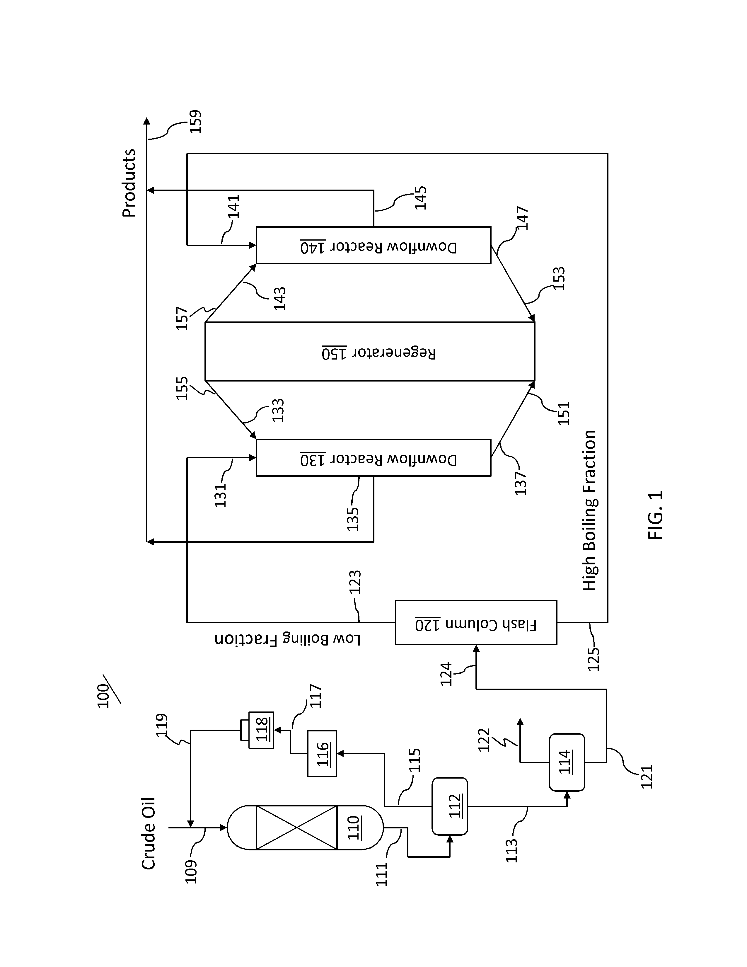
The patent describes a system and process that combines a hydroprocessing zone with an FCC zone to directly process crude oil to produce petrochemicals like olefins and aromatics. This results in a crude oil that has a reduced content of contaminants, is more paraffinic, has a lower BMCC, and has a higher API gravity. The crude oil is separated into low and high boiling fractions, which are then cracked in separate reactors to produce cracked products and spent catalyst. The spent catalyst from both reactors is regenerated and the cracked product streams are recovered. The patent also mentions that crude oil can be pre-treated before being processed using the system and process described in the patent.

Problems solved by technology

In addition, two-phase flow of reactants over a fixed bed of catalyst often creates maldistribution within the reaction zone with the concomitant inefficient utilization of catalyst and incomplete conversion of the reactants.
Momentary misoperation or electrical power failure can also cause severe catalyst coking which may require the process to be shut down for catalyst regeneration or replacement.
However, certain drawbacks of FCC processes include relatively low hydrogenation and relatively high reaction temperatures that tend to accelerate coke formation on the catalyst and requiring continuous regeneration.

Method used


Image

  • Integrated hydroprocessing and fluid catalytic cracking for processing of a crude oil
  • Integrated hydroprocessing and fluid catalytic cracking for processing of a crude oil
  • Integrated hydroprocessing and fluid catalytic cracking for processing of a crude oil

Examples


example

[0044]As an example an Arab Light crude oil was hydrotreated according to the conditions in Table 1 below:

TABLE 1Hydrotreatment ConditionsTemperature (° C.)LHSV (h−1)Pressure (bar)3700.5100-150

[0045]The properties of the initial feed and the hydrotreated product are reported in Table 2 below. The hydroprocessed feed is fractionated into two fractions at 350° C. and both fractions are then sent to the two downer HS-FCC unit. The properties of the 350° C.+fraction are also reported in Table 2.

TABLE 2Properties of Arab Light, upgraded Arab Light and its 350° C.+ fractionSulfurNitrogenNickelVanadiumConCarbonSample(wt %)(ppm)(ppm)(ppm)(wt %)DensityArab Light1.94961140.8584Hydrotreated Arab Light0.280399.0612.00.8581350° C.+0.540NA6.86.32.80.937


PUM

PropertyMeasurementUnit
pressureaaaaaaaaaa
temperatureaaaaaaaaaa
operating temperatureaaaaaaaaaa

Abstract

An integrated hydroprocessing and fluid catalytic cracking process is provided for the direct processing of a crude oil to produce olefinic and aromatic petrochemicals. Crude oil and hydrogen are charged to a hydroprocessing zone operating under conditions effective to produce a hydroprocessed effluent having a reduced content of contaminants, an increased paraffinicity, reduced Bureau of Mines Correlation Index, and an increased American Petroleum Institute gravity. The hydroprocessed effluent is separated into a low boiling fraction and a high boiling fraction. The low boiling fraction is cracked in a first downflow reactor of a fluid catalytic cracking unit in the presence of a predetermined amount of catalyst to produce cracked products and spent catalyst, and the high boiling fraction is cracked in a second downflow reactor of the fluid catalytic cracking unit in the presence of a predetermined amount of catalyst to produce cracked products and spent catalyst. Spent catalyst from both the first and second downflow reactors are regenerated in a common regeneration zone, and first and second cracked product streams are recovered.

Description

RELATED APPLICATIONS[0001]This application claims the benefit of priority of U.S. Provisional Patent Application Nos. 61 / 613,228 filed Mar. 20, 2012 and 61 / 789,871 filed Mar. 15, 2013, which are incorporated by reference herein.BACKGROUND OF THE INVENTION[0002]1. Field of the Invention[0003]The present invention relates to an integrated hydroprocessing and fluid catalytic cracking process for production of petrochemicals such as olefins and aromatics from feeds including crude oil.[0004]2. Description of Related Art[0005]Compositions of natural petroleum or crude oils are significantly varied based on numerous factors, mainly the geographic source, and even within a particular region, the composition can vary. Crude oils are refined to produce transportation fuels and petrochemical feedstocks. Typically fuels for transportation are produced by processing and blending of distilled fractions from the crude to meet the particular end use specifications. After initial atmospheric and / or...

Claims


Application Information

Patent Timeline
Patent Type & Authority Applications(United States)
IPC IPC(8): C10G69/04C10G51/06
CPCC10G11/18C10G2300/70C10G45/02C10G69/04C10G51/06C10G2400/20
Inventor ABBA, IBRAHIM A.SHAFI, RAHEELBOURANE, ABDENNOURSAYED, ESSAM
Owner SAUDI ARABIAN OIL CO
Learn More