
Fuel cell separator material, fuel cell, and method for manufacturing fuel cell separator material

a technology of separator material and fuel cell, which is applied in the manufacture of final products, cell components, electrochemical generators, etc., can solve the problems of difficult to secure sufficient sealing performance, poor adhesion of carbon-based electroconductive layer to general adhesives, and greatly affected sealing performance of separators used. , to achieve excellent adhesion to gasket materials, excellent excellent effect of electroconductivity and corrosion resistan

Inactive Publication Date: 2013-09-26
KOBE STEEL LTD
View PDF4 Cites 0 Cited by
  • Summary
  • Abstract
  • Description
  • Claims
  • Application Information

AI Technical Summary

Benefits of technology

The present invention is aimed at providing a fuel cell separator material that is highly conductive and resistant to corrosion, and is capable of tightly adhering to a gasket material. This is achieved by proposing a novel separator material, a fuel cell, and a method for manufacturing the fuel cell separator material. The technical effects of this invention are improved performance and durability of the fuel cell, and simplified manufacturing process.

Problems solved by technology

Although these have excellent corrosion resistance, because they are inferior in strength and toughness, they may be broken when vibration and impact are applied.
However, the technologies related to said Japanese Patent No. 4486801 to JP-A No. 2003-56704 are technologies on adhesives adhering a separator and a gasket material to each other or on a gasket material and are not technologies on the separator itself, and therefore, according to these technologies, sealing performance is greatly affected by the separator used.
Also, in order to improve the electroconductivity and corrosion resistance of a separator at a low cost, technologies of coating a carbon-based electroconductive layer on metallic material were tried, however there was a problem that the carbon-based electroconductive layer was inferior in adhesiveness to adhesives in general and sufficient sealing performance was hard to be secured.

Method used

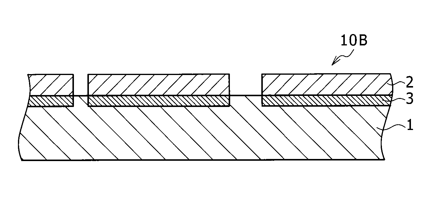
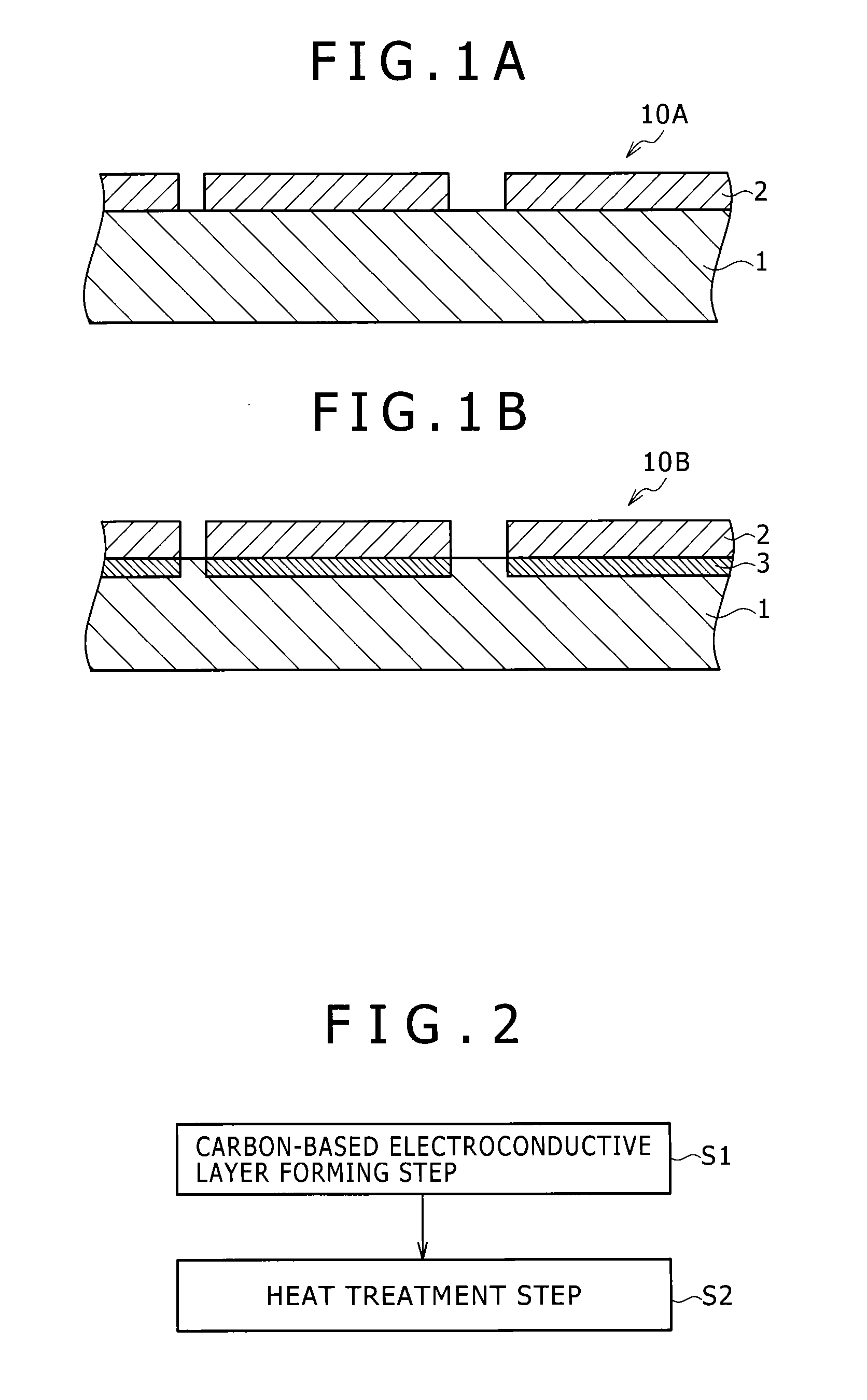
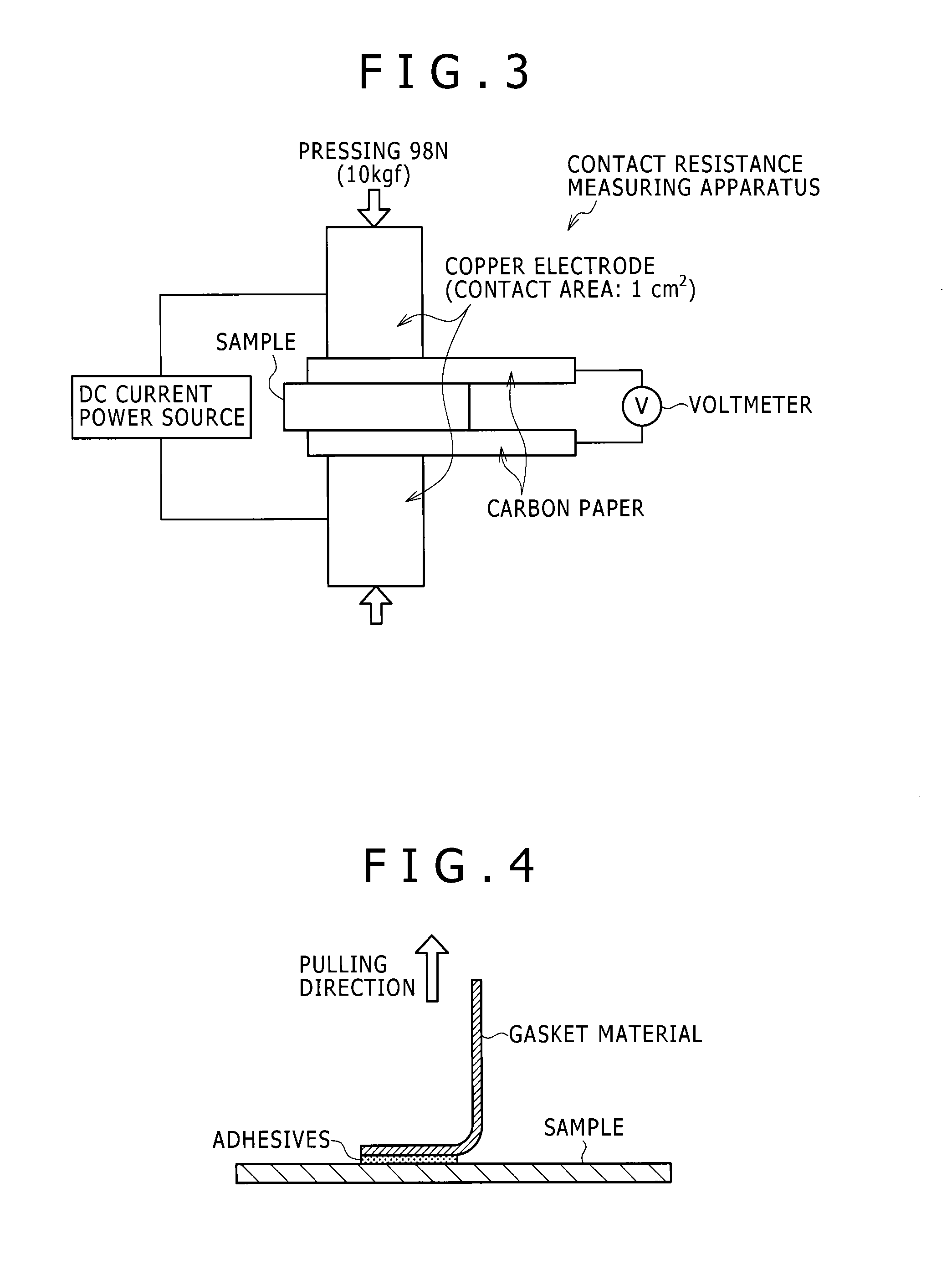

Image

  • Fuel cell separator material, fuel cell, and method for manufacturing fuel cell separator material
  • Fuel cell separator material, fuel cell, and method for manufacturing fuel cell separator material
  • Fuel cell separator material, fuel cell, and method for manufacturing fuel cell separator material

Examples


examples

[0092]Next, the fuel cell separator material in relation with the present invention will be described specifically comparing examples satisfying the requirement of the present invention and comparative examples not satisfying the requirement of the present invention.

[Preparation of Sample (Sample Nos. 1-13)]

[0093]For the substrate, a titanium substrate of JIS H 4600 type 1 was used.

[0094]The chemical composition of the titanium substrate (annealing-pickling-finished) was O: 450 ppm, Fe: 250 ppm, N: 40 ppm, with the remainder being Ti and unavoidable impurities, the sheet thickness of the titanium substrate was 0.1 mm, and the size was 50×150 mm. The titanium substrate was obtained by subjecting titanium raw material to conventional publicly known melting step, casting step, hot rolling step, and cold rolling step.

[0095]Next, a method for forming the carbon-based electroconductive layer will be described, however, because the method for forming the carbon-based electroconductive laye...


PUM

PropertyMeasurementUnit
thicknessaaaaaaaaaa
thicknessaaaaaaaaaa
apparent densityaaaaaaaaaa

Abstract

It is an object to provide a fuel cell separator material excellent in electroconductivity and corrosion resistance and capable of excellently adhering to a gasket material by stipulating a novel separator material, a fuel cell, and a method for manufacturing the fuel cell separator material.In a fuel cell separator material in which a carbon-based electroconductive layer including graphite is formed on the surface of a substrate formed of pure titanium or a titanium alloy, a coating rate of the carbon-based electroconductive layer is 20-70% when a range of 550×400 μm is observed with 200 times observation magnification using an electron microscope.

Description

BACKGROUND OF THE INVENTION[0001]1. Field of the Invention[0002]The present invention relates to a fuel cell separator material, a fuel cell, and a method for manufacturing the fuel cell separator material, and relates specifically to a fuel cell separator material constituted so as to include a substrate formed of titanium or titanium alloy, a fuel cell, and a method for manufacturing the fuel cell separator material.[0003]2. Description of the Related Art[0004]A fuel cell capable of continuously taking out electric power by continuously supplying fuel such as hydrogen and the like and an oxidizing agent such as oxygen and the like has high power generating efficiency unlike a primary battery such as a dry cell and the like and a secondary battery such as a lead storage battery and the like and is not affected much by the magnitude of the scale of the system, noise and vibration are less, and therefore the fuel cell is expected as an energy source covering various uses and scales. ...

Claims


Application Information

Patent Timeline
Patent Type & Authority Applications(United States)
IPC IPC(8): H01M8/02
CPCH01M8/0204Y02E60/50H01M8/0228H01M8/0213H01M8/0206Y02P70/50H01M8/02
Inventor SUZUKI, JUNSATO, TOSHIKI
Owner KOBE STEEL LTD
Learn More