
Function layer ink, method for manufacturing light-emitting element, light-emitting device, and electronic apparatus

Active Publication Date: 2013-10-03
SEIKO EPSON CORP
View PDF34 Cites 36 Cited by
  • Summary
  • Abstract
  • Description
  • Claims
  • Application Information

AI Technical Summary

Benefits of technology

The patent text describes a method for controlling the drying process of ink on a function layer, which helps to prevent the ink from spreading or sticking during the drying process. This method involves using solvents that evaporate at different rates, resulting in a gradual increase in the viscosity of the ink and a reduction in the drying speed. This slows down the interaction between molecules in the ink, resulting in a more uniform and thicker layer. The patent also describes an electronic device that includes this light-emitting device, which can be used for information or illumination purposes.

Problems solved by technology

This makes it difficult to form a luminescent layer having a uniform thickness.
In addition, the aggregation of the material may result in failure in forming the luminescent layer and cause emission failure.
In other words, it is difficult to form a luminescent layer having desired optical properties with a high yield.

Method used


Image

  • Function layer ink, method for manufacturing light-emitting element, light-emitting device, and electronic apparatus
  • Function layer ink, method for manufacturing light-emitting element, light-emitting device, and electronic apparatus
  • Function layer ink, method for manufacturing light-emitting element, light-emitting device, and electronic apparatus

Examples


first embodiment

Droplet Ejection Apparatus

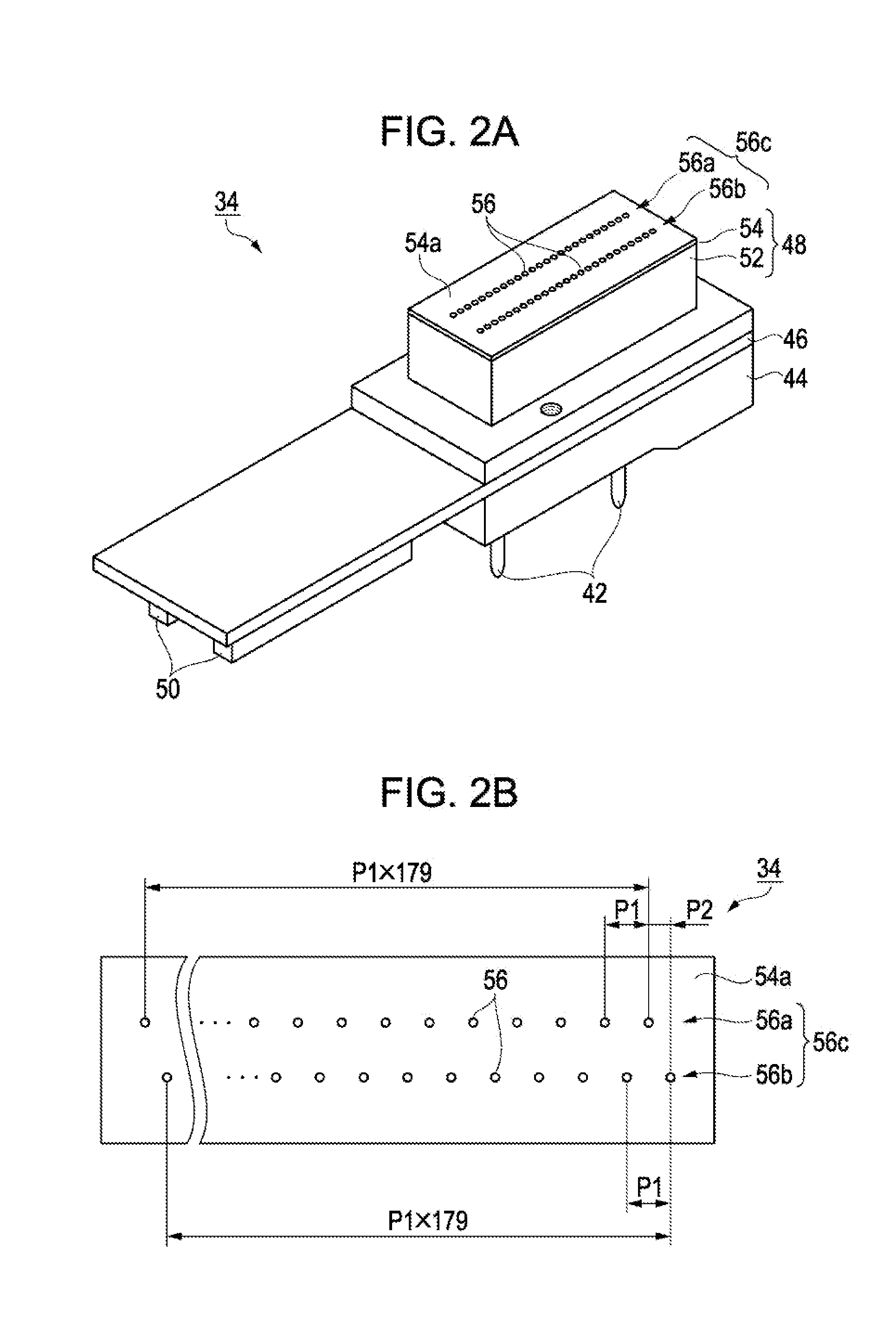
[0042]An ejection apparatus that can eject droplets of a liquid containing a function layer material onto an ejection target will first be described with reference to FIGS. 1 to 4.

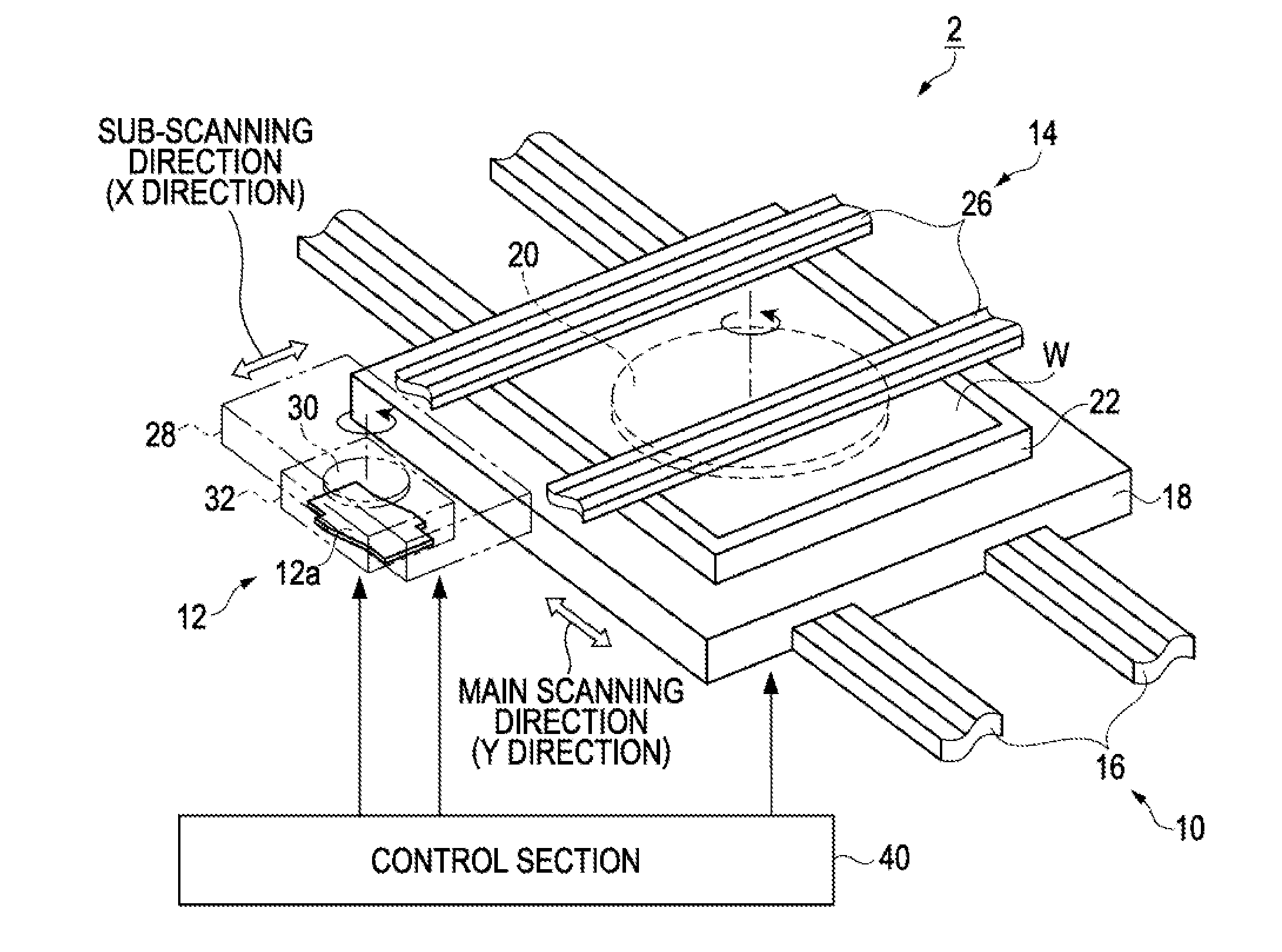
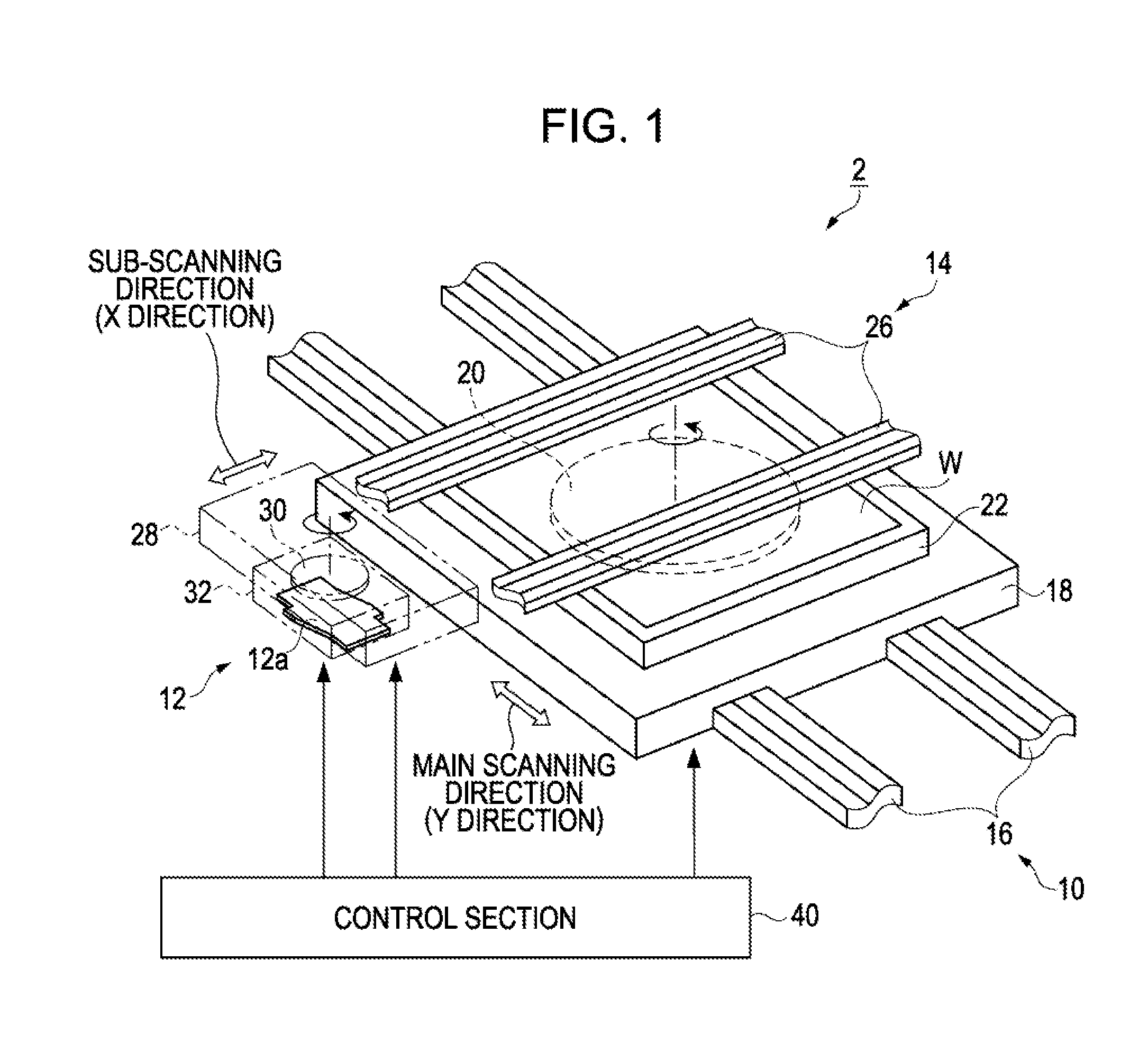
[0043]FIG. 1 is a schematic perspective view of an election apparatus according to an embodiment. As shown in FIG. 1, the election apparatus 2 of the embodiment includes a work transport mechanism 10 that transports a planar work W, which is an ejection target, in a first direction, or a main scanning direction (Y direction), of the work W, and a head transport mechanism 14 that transports a head unit 12 in a second direction, or a sub scanning direction (X direction), perpendicular to the main scanning direction.

[0044]The work transport mechanism 10 includes a pair of guide rails 16, a movable platen 18 that moves along the pair of guide rails 16, and a stage 22 disposed on the movable platen 18. A work W is placed on the stage with a rotation mechanism 20 therebetween.

[0045]The ...

example 1

[0151]First, hole injection layers were formed by an ink jet method to a thickness of 50 to 60 nm on a substrate provided with anode layers thereon. After being vacuum dried, the coating was fired by heating at 150° C. The hole injection layer material was PEDOT / PSS (1 / 20) that had been prepared by dispersing poly(3,4-ethylenedioxythlophene), which is a polythiophene derivative, in a disperse medium polystyrene sulfonic acid to prepare a dispersion, and further dispersing the dispersion in water. At this time, in order to perform stable ejection, a solvent having a high boiling point was added to the macromolecular PEDOT / PSS. Examples of the solvent having a high boiling point include aromatic hydrocarbons, isopropyl alcohol (IPA), n-butanol, γ-butyrolactone, N-methylpyrrolidone (NMP), dimethylformamide (DMF), hexamethylphosphoramide (HMPA), dimethyl sulfoxide (DMSO), 1,3-dimethyl-2-imidazolidinone (DMI) and its derivatives, and glycol ethers such as Carbitol acetate and butyl Carbi...

example 2

[0154]Luminescent layers were formed using solutions each containing 1.5% by weight of any of the same red, green and blue low-molecular-weight luminescent materials as in Example 1 in a mixed solvent (aqueous solvent A+aqueous solvent B, shown in the table of FIG. 10C). Other steps in the process for manufacturing the organic EL elements of Example 2 were the same as in Example 1.


PUM

PropertyMeasurementUnit
Temperatureaaaaaaaaaa
Percent by massaaaaaaaaaa
Dynamic viscosityaaaaaaaaaa

Abstract

A function layer ink used for forming a function layer by a liquid coating process contains a function layer material containing a macromolecular material or a low-molecular-weight material, and a mixed solvent containing solvent A and solvent B. Solvent A has a viscosity in the range of 0.01 to 0.05 Pa·s, and solvent B has a viscosity of less than 0.01 Pa·s and a lower boiling point than solvent A. The mixed solvent has a viscosity of less than 0.02 Pa·s and a boiling point in the range of 200 to 350° C., and contains 0.1% to 10% by weight of solvent A.

Description

BACKGROUND[0001]1. Technical Field[0002]The present invention relates to a function layer ink used for forming a function layer, a method for manufacturing a light-emitting element, and a light-emitting device and an electronic apparatus.[0003]2. Related Art[0004]An organic electroluminescent element (light-emitting element) has a structure including at least one light-emitting organic layer (luminescent layer) between an anode and a cathode. In light-emitting elements of this type, electrons and holes are injected to the luminescent layer respectively from the cathode and the anode by applying an electric field between the cathode and the anode, and the electrons and the holes form excitons in the luminescent layer. When the excitons disappear (when electrons and holes are recombined with each other), part of the energy is emitted as fluorescence or phosphorescence.[0005]In general, a light-emitting element has a hole injection layer on the anode, and a hole transport layer or a lu...

Claims


Application Information

Patent Timeline
IPC IPC(8): H01L51/00
CPCH01L51/0037H01L51/0007H01L51/0005H10K71/135H10K71/15H10K85/1135H10K71/236H10K71/441H10K71/00C09D11/36
Inventor WATANABE, SHOTARO
Owner SEIKO EPSON CORP
Learn More