High frequency transition matching in an electronic package for millimeter wave semiconductor dies

a technology of high frequency transition matching and millimeter wave semiconductor, applied in the field of electronic packaging, can solve the problems of increasing the size of the package, affecting the transmission of low frequency signals to the electronic circuit board, and extremely sensitive millimeter wave signals to manufacturing inaccuracies

Active Publication Date: 2013-10-03
AY DEE KAY LLC DBA INDIE SEMICON
View PDF5 Cites 36 Cited by
  • Summary
  • Abstract
  • Description
  • Claims
  • Application Information

AI Technical Summary

Benefits of technology

[0017]There is also provided in accordance with the invention, a method of high frequency chip to circuit board transition, the method comprising providing a semiconductor chip comprising a ground plane, a first high frequency pad and a plurality of first ground pads, providing a high frequency circuit board constructed from a dielectric material, the high frequency circuit board comprising a ground plane, a second high frequency pad and a plurality of second ground pads, placing at least one high frequency bump to electrically

Problems solved by technology

Millimeter wave signals, thus, are extremely sensitive to manufacturing inaccuracies.
In addition, conventional mmWave packages use complex assembly processes.
These waveguide interfaces must be mounted using screws to other waveguide interfaces (such as to other modules or antenna) which increases the package's size and complicates the transmission of low frequency signals to the electronic circuit board.
Despite the advantages described above, SMT packages have two main drawbacks in the high frequency bands such as mmWave that cause high electrical losses.
A first drawback is that SMT packages include printed transmission lines such as microstrip or strip lines which exhibit high loss at high frequencies compared with waveguides, and thus a waveguide interface is preferred at those frequencies

Method used


Image

  • High frequency transition matching in an electronic package for millimeter wave semiconductor dies
  • High frequency transition matching in an electronic package for millimeter wave semiconductor dies
  • High frequency transition matching in an electronic package for millimeter wave semiconductor dies

Examples


embodiment

Electronic Package Embodiment

[0033]An electronic packaging system for millimeter wave semiconductor chips provides electrical connections between a millimeter wave semiconductor chip and an electric circuit board, while providing heat dissipation and a mechanical protective environment. The configuration of the package enables the use of standard reflow solder processes for attachment to a printed circuit board.

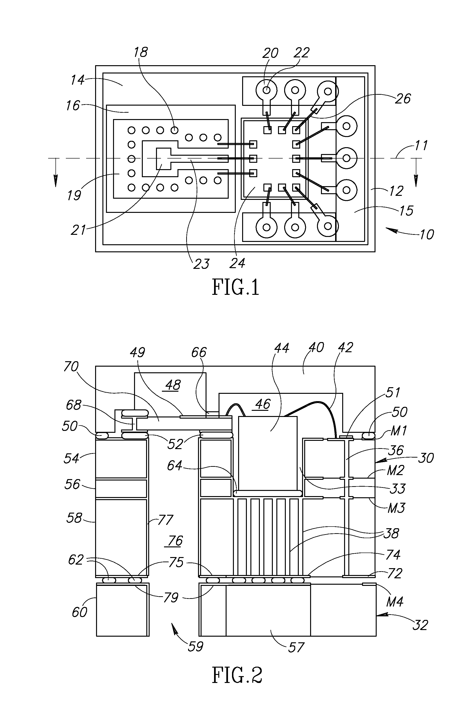
[0034]A top view of a multilayer circuit board, semiconductor chip and high frequency (HF) circuit board connected with wire bonds is shown in FIG. 1. The present invention is a combination of an SMT package, a waveguide interface and low cost production and assembly into a single device which enjoys advantages of each of the above technologies while eliminating their drawbacks.

[0035]The package, generally referenced 10, comprises a multilayer circuit board 14, constructed out of any suitable material such as FR4, semiconductor die 24 mounted on the multilayer circuit board, ...


PUM


Abstract

A mmWave electronics package constructed from common Printed Circuit Board (PCB) technology and a metal cover. Assembly of the package uses standard pick and place technology and heat is dissipated directly to a pad on the package. Input/output of mmWave signal(s) is achieved through a rectangular waveguide. Mounting of the electronic package to an electrical printed circuit board (PCB) is performed using conventional reflow soldering processes and includes a waveguide I/O connected to an mmWave antenna. The electronic package provides for transmission of low frequency, dc and ground signals from the semiconductor chip inside the package to the PCB it is mounted on. An impedance matching scheme matches the chip to high frequency board transition by altering the ground plane within the chip. A ground plane on the high frequency board encircles the high frequency signal bump to confine the electromagnetic fields to the bump region reducing radiation loss.

Description

FIELD OF THE INVENTION[0001]The present invention relates to the field of electronic packaging, and more particularly relates to a method and apparatus for impedance matching a high frequency transition in an electronic packaging system for millimeter wave semiconductor dies.BACKGROUND OF THE INVENTION[0002]Extremely high frequency or EHF is the highest radio frequency band and runs the range of frequencies from 30 to 300 GHz. The frequencies in this band have a wavelength of ten to one millimeter, giving it the name millimeter band or millimeter wave (mmWave). In high frequency mmWave circuits, the wavelengths involved are shorter compared to the wavelengths of lower frequencies, which are more commonly used. Thus, the loss per unit length is higher due to radiation, scattering and absorption. Millimeter wave signals, thus, are extremely sensitive to manufacturing inaccuracies. In order to overcome these difficulties, high quality expensive materials and technologies (e.g., ceramic...

Claims


Application Information

Patent Timeline
IPC IPC(8): H01L23/66H01L23/00
CPCH01L23/66H01L24/81H01L2924/1517H01L2924/15153H01L2224/81801H01L2224/73265H01L2224/73253H01L2224/73207H01L2224/48235H01L2223/6616H01L2223/6633H01L2223/6683H01L2924/30107H01L2924/3011H01L2224/16225H01L2224/32235H01L24/16H01L24/32H01L24/48H01L24/73H01L2224/131H01L2224/16227H01L2224/48227H01L2924/00014H01L2924/014H01L2924/00H01L2224/05554H01P5/107H01L24/49H01L2224/49171H01L2224/45099H01L2224/45015H01L2924/207
Inventor DANNY, ELADNOAM, KAMINSKIKEISHI, OKAMOTOEVGENY, SHUMAKERKAZUSHIGE, TORIYAMA
Owner AY DEE KAY LLC DBA INDIE SEMICON
Why Eureka
Try Eureka