
Versatile zero-voltage switch resonant inverter for industrial dielectric barrier discharge generator applications

a zero-voltage switch and generator technology, applied in the direction of lighting apparatus, electrical equipment, light sources, etc., can solve the problems of space-provider constraints, performance and reliability expectations, etc., and achieve the effect of superior dynamic range and stability

Active Publication Date: 2013-10-03
MKS INSTR INC
View PDF2 Cites 61 Cited by
  • Summary
  • Abstract
  • Description
  • Claims
  • Application Information

AI Technical Summary

Benefits of technology

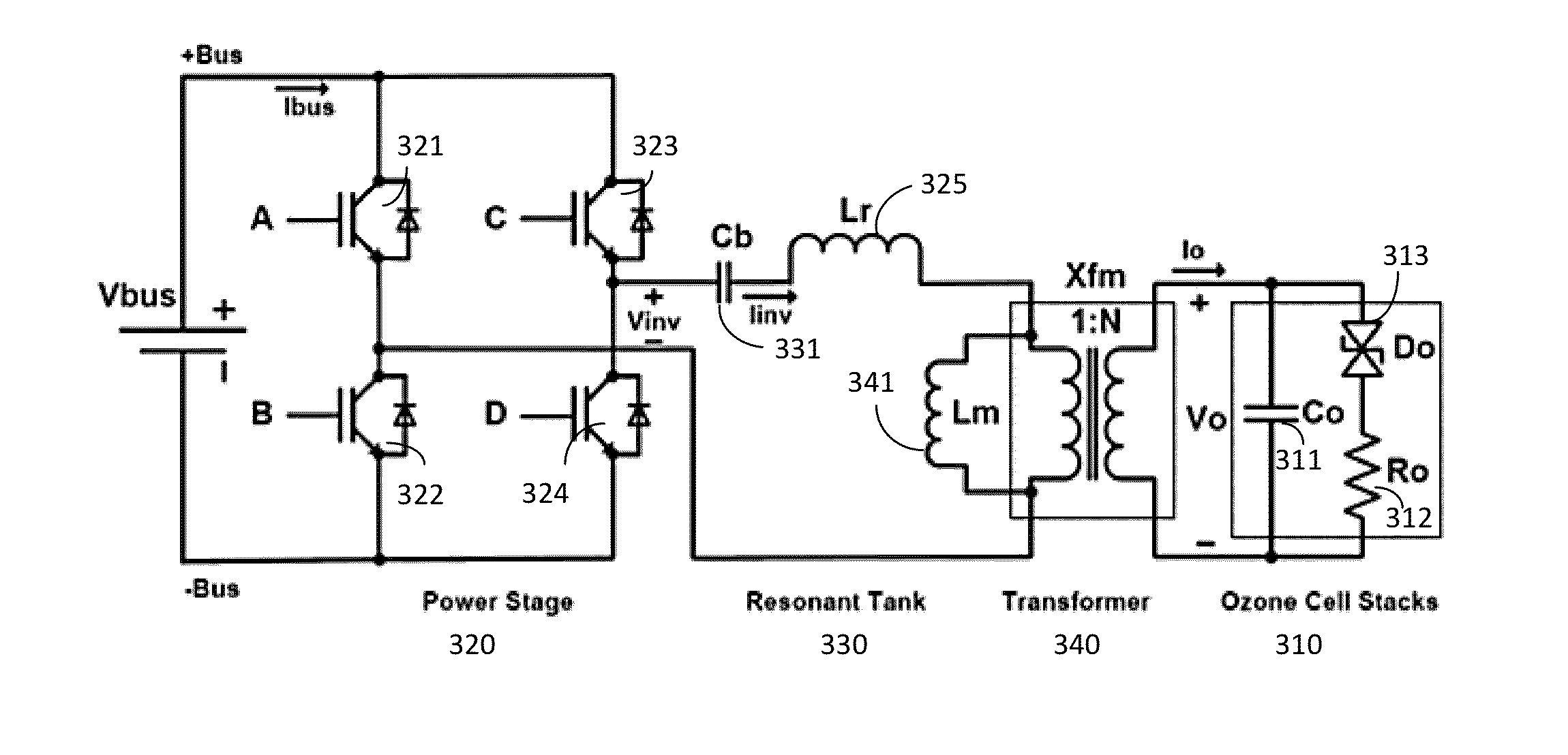
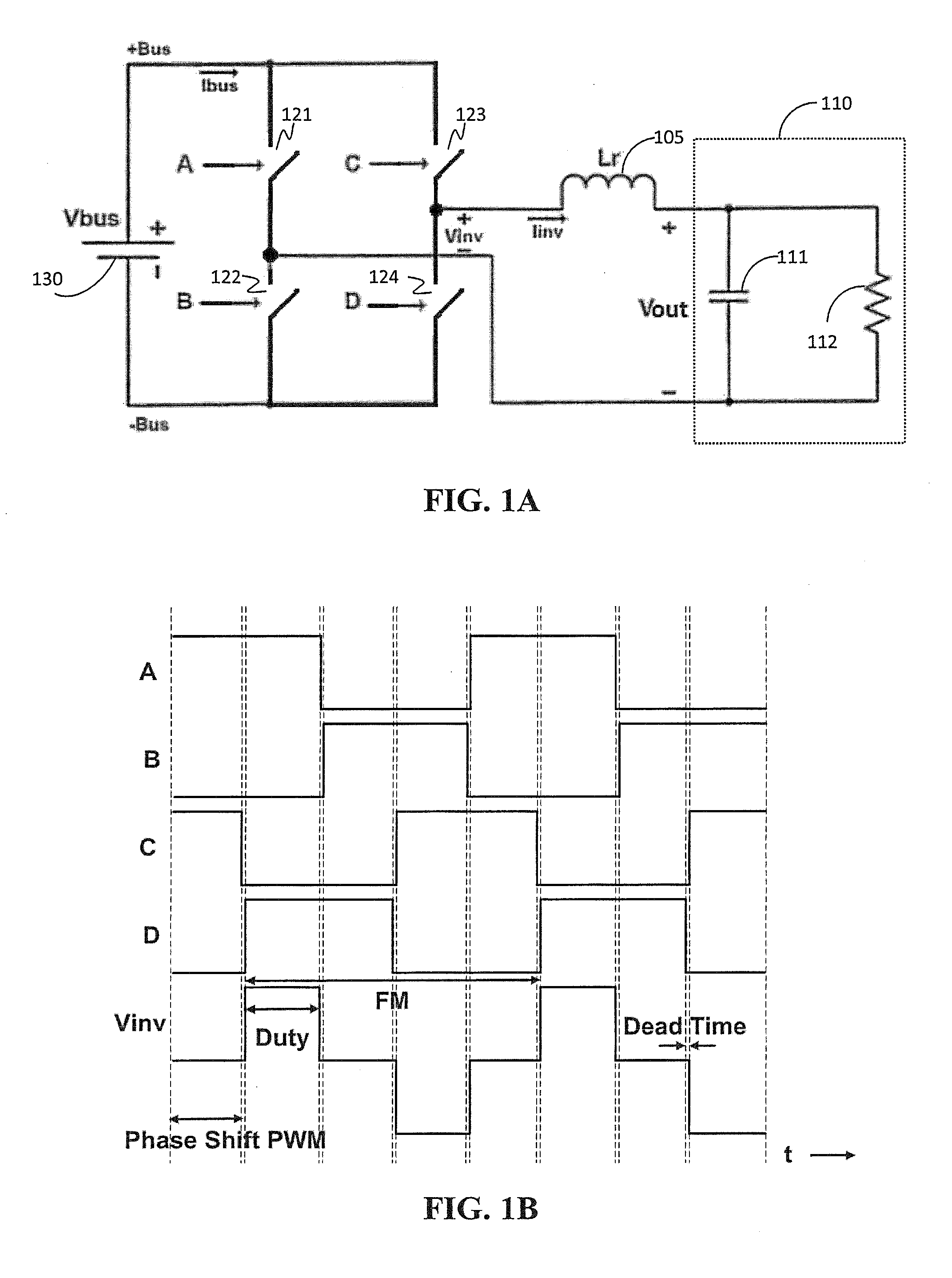
The patent describes a power system that uses a dual resonant inverter power stage with a parallel resonant topology and a combined pulse width modulation (PWM) and frequency modulation (FM) control scheme. This allows for superior dynamic range and stability even at light loads. The technical effects of this system include improved efficiency, dynamic range, and stability.

Problems solved by technology

Although increasing output power increases ozone concentration, expectations of performance and reliability and limitations on space provide constraints that are often in opposition.

Method used


Image

  • Versatile zero-voltage switch resonant inverter for industrial dielectric barrier discharge generator applications
  • Versatile zero-voltage switch resonant inverter for industrial dielectric barrier discharge generator applications
  • Versatile zero-voltage switch resonant inverter for industrial dielectric barrier discharge generator applications

Examples


example 1

Light Load

[0074]The simulation results for the current loop at light load are shown in FIGS. 11A-11C and the experimental results for the current loop at light load is shown in FIG. 11D. FIG. 11A shows that Vbus was set at 350 V, and the light load conditions show output load power being less than 25 W (compare to ˜250 W output power light load condition of 5% ozone concentration of a 5 kW system's maximum output). FIG. 11B shows a plot of the inverter stage output voltage (Vinv) and current (Iinv). FIG. 11C shows a plot of the power stage output voltage (Vout) and current (Iout) (i.e., the voltage and current being supplied to the ozone cell(s)). FIG. 11D shows the scope waveforms of the inverter stage output voltage Vinv and current Iinv for the experimental system where Vbus=300 V, Ibus=0.8 A, Pin=240 W. As illustrated by FIG. 11C and confirmed by the waveforms shown in FIG. 11D, the combination of PWM and FM control enable soft switching even at light loads. It should be noted t...

example 2

Full Load

[0075]The simulation results for the current loop at full load are shown in FIGS. 12A-12C and the experimental results for the current loop at 110% of full load is shown in FIG. 12D. FIG. 12A shows that Vbus was set at 350 V, and the full load conditions show output load power being at about 5.5 kW (single stage). FIG. 12B shows a plot of the inverter stage output voltage (Vinv) and current (Iinv). FIG. 12C shows a plot of the power stage output voltage (Vout) and current (Iout) (i.e., the voltage and current being supplied to the ozone cell(s)). FIG. 12D shows the scope waveforms of the inverter stage output voltage Vinv and current Iinv for the experimental system where Vbus=300 V, Ibus=18.3 A, Pin=˜5.5 kW. As illustrated by FIG. 12C and confirmed by the waveforms shown in FIG. 12D, the combination of PWM and FM control enable soft switching and increased output power.


PUM


Abstract

A power system for a dielectric barrier discharge system, such as used for generating ozone, can include a full bridge inverter stage and parallel resonant tank outputting a signal for powering a dielectric barrier discharge cell stack. The inverter stage is controlled using a combination of pulse width modulation (PWM) and frequency modulation (FM) to enable soft switching through all load conditions—from full load to light load. A current control loop error amplifier compensator can provide a duty cycle adjustment signal to a phase shift PWM controller chip that generates the switching signals for the inverter stage. A feedback signal is also used to adjust a clock frequency time constant of the PWM controller chip to provide the FM. In one embodiment, the feedback signal is an output of an inverting amplifier connected at an output of the current control loop error amplifier compensator.

Description

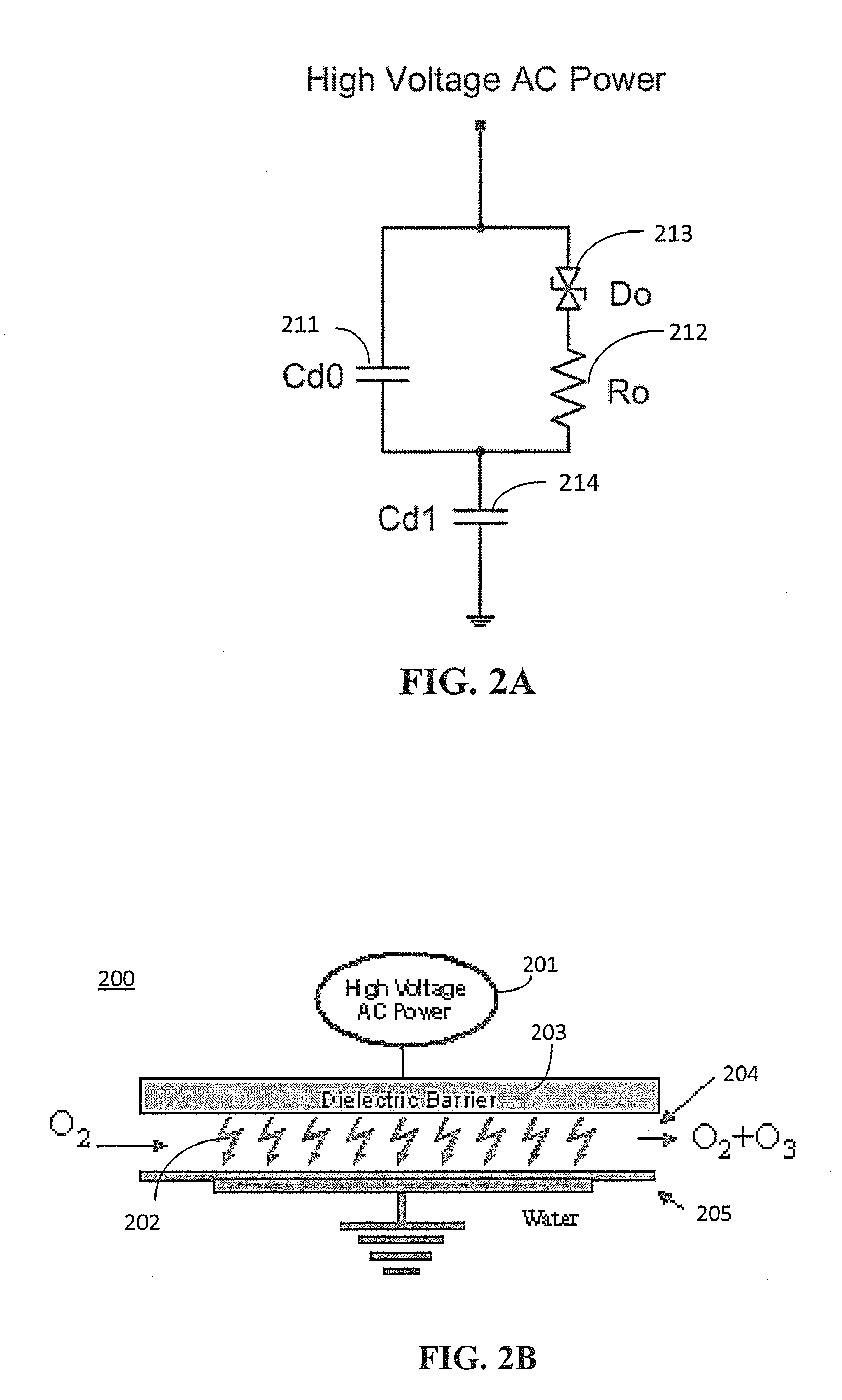
BACKGROUND OF THE INVENTION[0001]Ozone is used for many industrial and semiconductor processing applications including, for example, cleaning semiconductor wafers and the process chambers of semiconductor processing equipment; producing insulating films on semiconductor wafers; and disinfecting water, food, and other consumable or industrial products.[0002]One technique for ozone generation involves a dielectric barrier discharge, where high purity oxygen is exposed to an electrical discharge created by the application of high voltage AC power. The electrical discharge breaks down the oxygen molecules into their atomic state, allowing the oxygen to recombine into a mixture of ozone (O3) and oxygen (O2). For this technique, ozone concentration is proportional to the output power of the ozone generating system. Although increasing output power increases ozone concentration, expectations of performance and reliability and limitations on space provide constraints that are often in oppos...

Claims


Application Information

Patent Timeline
IPC IPC(8): H05B41/24
CPCY02B20/348H05B33/0803H05B45/00Y02B20/30
Inventor TRAN, KENCHEN, XINGNEWMAN, RUSSELL L.LEE, FRANKLIN
Owner MKS INSTR INC
Learn More