Blink detection system for electronic ophthalmic lens

a detection system and electronic technology, applied in the field of powered or electronic ophthalmic lenses, can solve the problems of increasing the likelihood of creating wearable or embeddable microelectronic devices, affecting the clinical effect,

Active Publication Date: 2013-10-03
JOHNSON & JOHNSON VISION CARE INC
View PDF22 Cites 53 Cited by
  • Summary
  • Abstract
  • Description
  • Claims
  • Application Information

AI Technical Summary

Benefits of technology

[0017]The blink detection algorithm in accordance with the present invention overcomes the limitations associated with the prior art as briefly described above. More specifically, the blink detection algorithm of the present invention is able to...

Problems solved by technology

As electronic devices continue to be miniaturized, it is becoming increasingly more likely to create wearable or embeddable microelectronic devices for a variety of uses.
Early contact lenses were made or fabricated from hard materials, were relatively expensive and fragile.
In addition, these early contact lenses were fabricated from materials that did not allow sufficient oxygen transmission through the contact lens to the conjunctiva and cornea which potentially could cause a number of adverse clinical effects.
Although these contact lenses are still utilized, they are not suitable for all patients due to their poor initial comfort.
The proper combination of devices could yield potentially unlimited functionality; however, there are a number of difficulties associated with the incorporation of extra components on a piece of optical-grade polymer.
In general, it is difficult to manufacture such components directly on the lens for a number of reasons, as well as mounting and interconnecting planar devices on a non-planar surface.
It is also difficult to manufacture to scale.
It is also difficult to make a contact le...

Method used


Image

  • Blink detection system for electronic ophthalmic lens
  • Blink detection system for electronic ophthalmic lens
  • Blink detection system for electronic ophthalmic lens

Examples


Embodiment Construction

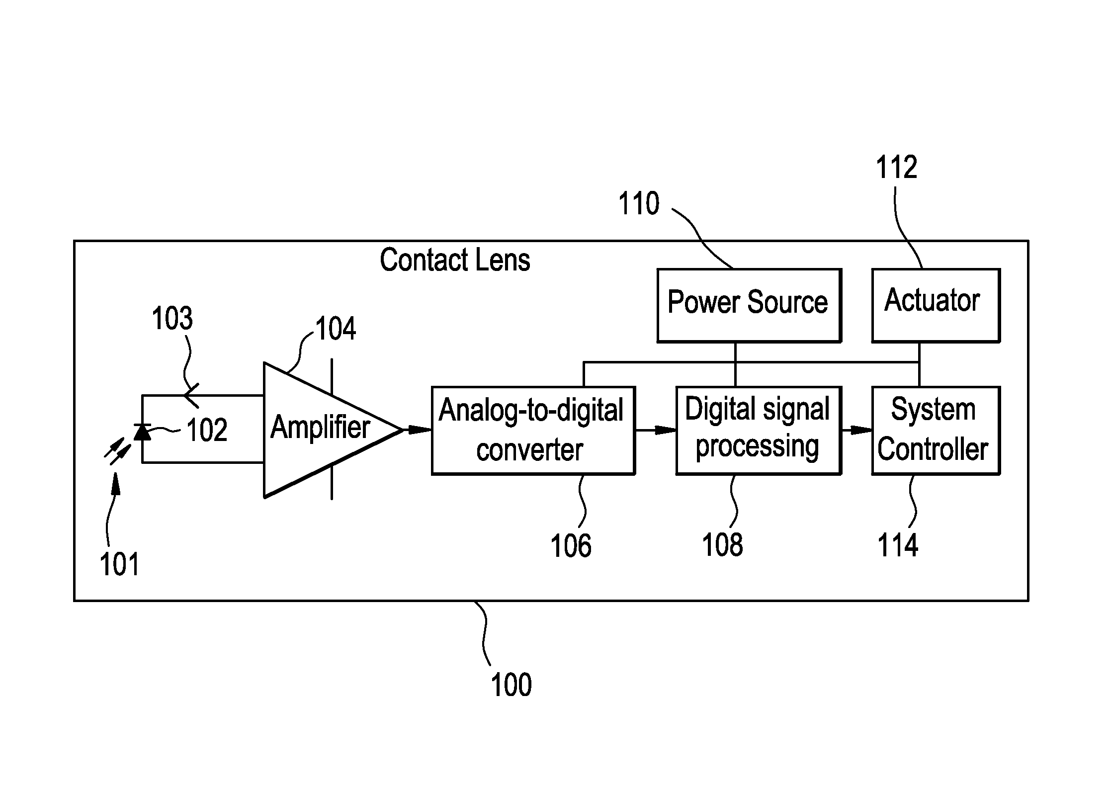
[0036]Conventional contact lenses are polymeric structures with specific shapes to correct various vision problems as briefly set forth above. To achieve enhanced functionality, various circuits and components may be integrated into these polymeric structures. For example, control circuits, microprocessors, communication devices, power supplies, sensors, actuators, light-emitting diodes, and miniature antennas may be integrated into contact lenses via custom-built optoelectronic components to not only correct vision, but to enhance vision as well as provide additional functionality as is explained herein. Electronic and / or powered contact lenses may be designed to provide enhanced vision via zoom-in and zoom-out capabilities, or just simply modifying the refractive capabilities of the lenses. Electronic and / or powered contact lenses may be designed to enhance color and resolution, to display textural information, to translate speech into captions in real time, to offer visual cues f...


PUM


Abstract

A blink detection algorithm and associated circuitry for an ophthalmic lens comprising an electronic system is described herein. The blink detection algorithm is implemented in the system controller which is part of an electronic system incorporated into the ophthalmic lens. The electronic system includes one or more batteries or other power sources, power management circuitry, one or more sensors, clock generation circuitry, control algorithms and circuitry, and lens driver circuitry. The blink detection algorithm implements the steps of sampling, at a predetermined rate, light incident on an eye of an individual and at least temporarily saving collected samples, determining when an eyelid is open or closed in order to divine the number, time period and pulse width of the blinks from the collected samples, calculating a number of blinks and the duration of the blinks in a given time period, and comparing the number of blinks, the durations of the blinks in the given time period, and the time between blinks in the given time period to a stored set of samples to determine patterns in blinking.

Description

CROSS REFERENCE TO RELATED APPLICATIONS[0001]This patent application claims the benefit of U.S. Provisional Patent Application No. 61 / 619,682, filed Apr. 3, 2012.BACKGROUND OF THE INVENTION[0002]1. Field of the Invention[0003]The present invention relates to a powered or electronic ophthalmic lens having a sensor and associated hardware and software for detecting when an individual blinks, and more particularly, to a sensor and associated hardware and software for detecting blinks and blink patterns in an individual to activate and control a powered or electronic ophthalmic lens.[0004]2. Discussion of the Related Art[0005]As electronic devices continue to be miniaturized, it is becoming increasingly more likely to create wearable or embeddable microelectronic devices for a variety of uses. Such uses may include monitoring aspects of body chemistry, administering controlled dosages of medications or therapeutic agents via various mechanisms, including automatically, in response to me...

Claims


Application Information

Patent Timeline
IPC IPC(8): A61B3/113
CPCA61B5/1103G02C7/04G06K9/00335A61B3/113G06K9/00885A61B5/0059A61B5/6821G02C7/083G02C7/049A61B5/7235F04C2270/041A61B3/10G06V40/20G06V40/10A61B3/125A61F2/14
Inventor PUGH, RANDALL BRAXTONTONER, ADAMHUMPHREYS, SCOTT ROBERTOTTS, DANIEL B.NEELEY, WILLIAM CHESTER
Owner JOHNSON & JOHNSON VISION CARE INC
Why Eureka
Try Eureka