Hybrid vehicle control device

Active Publication Date: 2013-10-03
NISSAN MOTOR CO LTD
View PDF1 Cites 29 Cited by
  • Summary
  • Abstract
  • Description
  • Claims
  • Application Information

AI Technical Summary

Benefits of technology

[0010]According to the present invention, the r

Problems solved by technology

When comparing with the required power by using the power value (value of several seconds) like this, despite the fact that the power value (instantaneous value) exceeds the required power, since the power value (value of several seconds) falls below the required

Method used


Image

  • Hybrid vehicle control device
  • Hybrid vehicle control device
  • Hybrid vehicle control device

Examples


Embodiment Construction

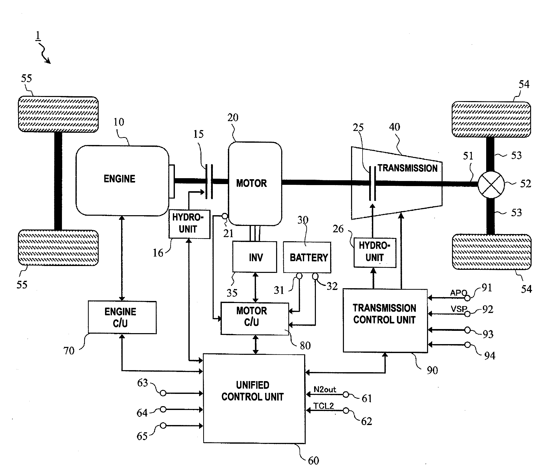
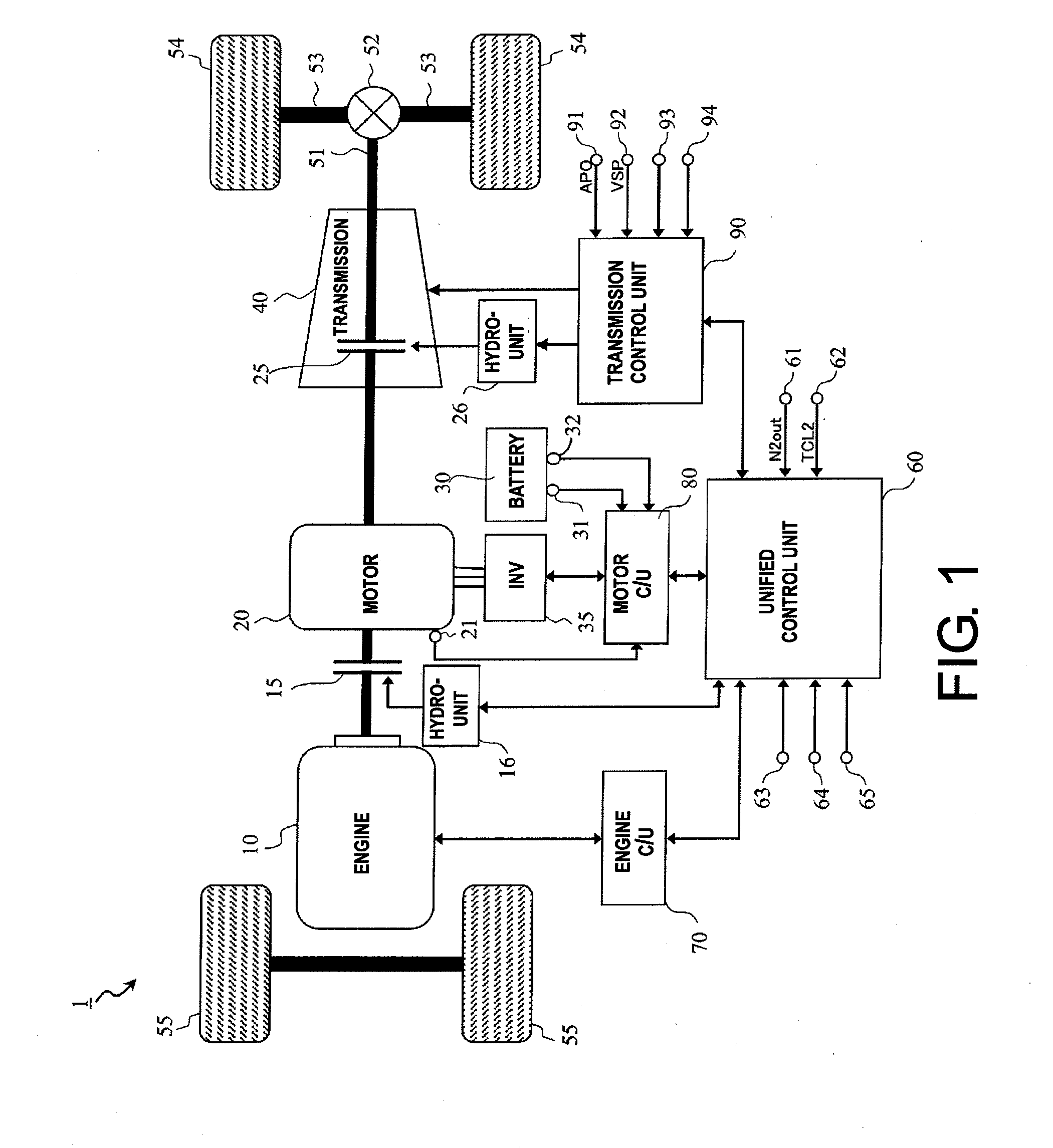
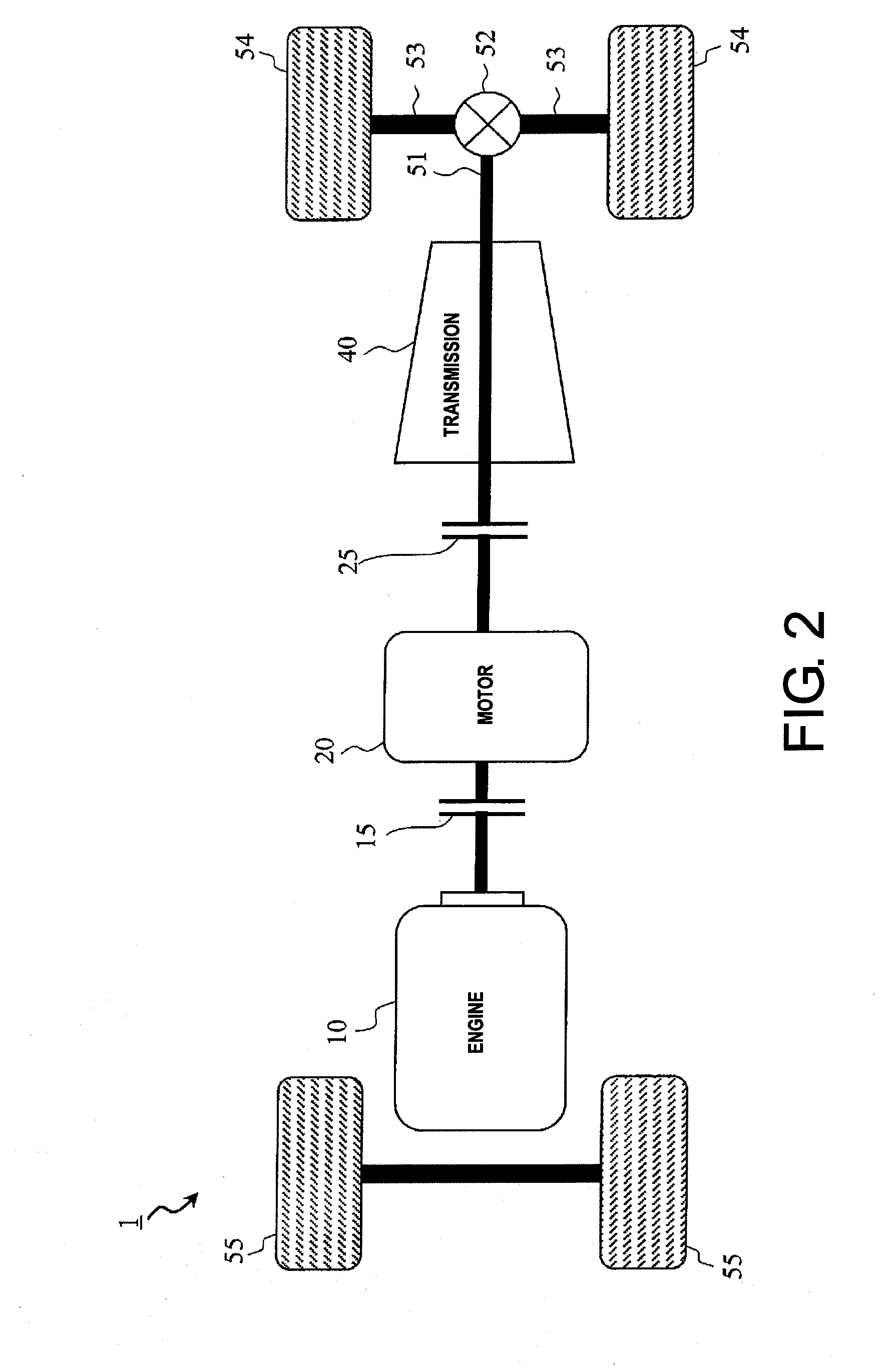
[0017]The hybrid vehicle 1 incorporating the control system of the embodiment according to the present invention is a vehicle of parallel system using a plurality of power sources such as an internal combustion engine and an electrically driven generator. As shown in FIG. 1. the hybrid vehicle 1 in the present embodiment is provided with an internal combustion engine (hereinafter referred to as “engine”), a first clutch 15, an electrically driven generator 20 (hereinafter “motor / generator”), a second clutch 25, a battery 30, an inverter 35, an automatic transmission 40, a propeller shaft 51, a differential gear unit 52, a drive shaft 53, and a pair of (left and right) drive wheels 54.

[0018]The engine 10 is one of the driving source that outputs a drive energy by burning gasoline, light oil, etc., and a valve openness of throttle valve or fuel injection amount of fuel injection valve, etc. is controlled based on the control signal from the engine control unit 70.

[0019]The first clutc...


PUM


Abstract

A control system is provided for controlling a hybrid vehicle that includes an internal combustion engine; an electric motor for starting the internal combustion engine; an inverter for controlling the electric motor; a clutch for selectively connecting and disconnecting power transmission between the internal combustion engine and the electric motor; and a battery for supplying power to the electric motor. The control device includes: a voltage detection unit for detecting the voltage of the battery a voltage control unit for controlling the output of the battery in accordance with a first power value currently available within the voltage limit range of the battery; and an internal combustion engine starting unit for engaging the clutch to start engine while controlling the inverter in accordance with the output from the battery that in turn is controlled by the voltage control unit.

Description

CROSS-REFERENCE TO RELATED APPLICATIONS[0001]This application is a U.S. National stage of International Application No. PCT / JP2011 / 072596, filed Sep. 30, 2011. This application claims priority to Japanese Patent Application No. 2010-241796, filed on Oct. 28, 2010. The entire disclosure of Japanese Patent Application No. 2010-241796 is hereby incorporated herein by reference.BACKGROUND[0002]1. Field of the Invention[0003]The present invention relates to a control device for a hybrid vehicle.[0004]2. Background Information[0005]In an engine start control system for a hybrid vehicle provided with at least an engine, a motor to start the engine, an inverter to control the motor, and a battery to supply power to the motor via the inverter, such a technology is known to control the rotation speed of the motor in order the available output power to exceed a required power at the time of engine starting based on the available output power or the potential power output with the battery and t...

Claims


Application Information

Patent Timeline
IPC IPC(8): B60W20/00B60W10/26B60W10/08B60W10/02B60W10/06B60L50/16
CPCB60K6/48Y02T10/70B60W10/02B60W10/06B60W10/08B60W10/26B60W20/00B60W30/192B60W50/029B60W50/038B60W50/045B60W2510/244B60W2710/081B60W2710/244B60W2710/248B60Y2400/3086F02D29/02F02N11/04F02N11/0862F02N2200/063Y02T10/6221Y02T10/6252Y02T10/6286Y02T10/7005Y02T10/7077B60L11/14B60W2600/00B60W20/40Y10S903/93F02N15/025F02N2011/0896F02N2200/064F02N2250/02B60L7/14B60L11/1859B60L11/1861B60L15/2009B60L2210/40B60L2220/14B60L2240/421B60L2240/423B60L2240/427B60L2240/441B60L2240/443B60L2240/545B60L2240/547B60L2240/549B60L2250/10Y02T10/7044Y02T10/705Y02T10/7241Y02T10/7275Y02T10/642B60K2006/4825B60L50/16B60L58/14Y02T10/62Y02T10/64Y02T10/72Y02T10/7072B60W20/13B60W2510/242B60W2556/00
Inventor TOKI, YOSHIMASA
Owner NISSAN MOTOR CO LTD
Why Eureka
Try Eureka