Electrochemical drilling system and process for improving electrical porosity of etched anode foil

a technology of etched anode foil and electrochemical drilling, which is applied in the manufacture of electrolytic capacitors, manufacturing tools, and electrolytic capacitors, etc., can solve the problems of reduced production downtime for routine cleaning, increased esr, and equivalent series resistance of capacitors, and reduce production downtime , the effect of less caustic cleaning of process equipmen

Active Publication Date: 2013-10-10
PACESETTER INC
View PDF5 Cites 12 Cited by
  • Summary
  • Abstract
  • Description
  • Claims
  • Application Information

AI Technical Summary

Benefits of technology

[0013]The methods and system described herein provide the advantage of a continuous ECD process, in which circulation of ECD solution to / from the bath achieves a substantially steady state concentration of dissolved aluminum, which by maintenance of the solution pH, does not precipitate into aluminum hydroxide. As a result, production downtime is reduced, since batch renewal of the ECD solution is avoided and caustic cleaning of the process equipment is less frequent.

Problems solved by technology

Energy storage density can be increased by using a multiple anode stack configuration element; however, the drawback is that the equivalent series resistance, ESR, of the capacitor increases as the conduction path from cathode to anode becomes increasingly tortuous.
This aluminum hydroxide solid should be filtered from solution if it is desired to process a plurality of foils'; otherwise, the electrochemical drilling solution becomes less effective in creating “through” type tunnels that improve electrical porosity.
Additionally, the aluminum hydroxide solid may build up on the process equipment, causing production downtime for routine cleaning (e.g., weekly) of the process equipment using a caustic solution.

Method used


Image

  • Electrochemical drilling system and process for improving electrical porosity of etched anode foil
  • Electrochemical drilling system and process for improving electrical porosity of etched anode foil
  • Electrochemical drilling system and process for improving electrical porosity of etched anode foil

Examples


example 1

200 Etched Foils

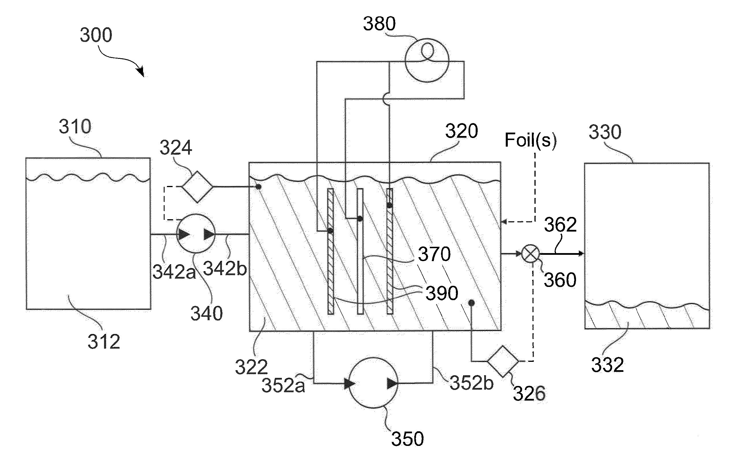
[0057]Rolls of etched aluminum foils were used. After an ECD station was caustic cleaned using the caustic cleaning procedure, the stock neutral ECD solution was heated to 95° C. Once at 95° C., 25 grams of sodium nitrate to the solution was added to the ECD tank. Additionally, 370 grams of 5.0% HCl was added to the solution in the ECD tank, to make the stock solution in the tank an acid ECD solution. The pH was measured after running 2 sets of dummy foils. The pH was about 2.0. The ECD time was set at 1 minute and 24 seconds at 63.0 amps. Every 10 foils, 44 grams of the 5.0% HCl solution was added to the ECD solution. If the pH increased above 2.7, a second 44 grams of 5.0% HCl solution was added.

[0058]At the end of the 200 foils, 1672 grams of 5.0% HCl was added to the tank not counting the initial 370 g add. Therefore, the estimated HCl needed per foil was 0.42 g / foil. The filter was inspected for solid build up. The amount of solids on the filter was very minimal...

example 2

200 Etched Foils

[0062]After the ECD station was caustic cleaned using a caustic cleaning procedure, the stock neutral ECD solution was heated to 95° C. Once at 95° C., 25 grams of sodium nitrate was added to the ECD tank, Additionally, 1000 grams of 5.0% HCl was added to the solution in the ECD tank, to make the stock solution in the tank an acid ECD solution. The pH was measured after running 6 sets of dummy foils. The pH was about 0.56. The ECD time was set at 1 minute and 45 seconds at 50.4 amps. Every 10 foils, 44 grams of the 5.0% HCl solution was added to the ECD solution. If the pH increased above 2.7, a second 44 grams of 5.0% HCl solution was added. At the end of the 200 foils, 1518 grams of 5.0% HCl was added to the tank not counting the initial 1000 g add. Therefore, the estimated HCl needed per foil was 0.38 g / foil. The filter was inspected for solid build up. The amount of solids on the filter was very minimal. The solution after 200 foils was slightly gray.

[0063]The se...

example 3

400 Etched Foils

[0066]The ECD station was not caustic cleaned using the caustic cleaning procedure before the experiment. Therefore, the experiment shows a worse case scenario of excess aluminum in the system.

[0067]Once at 95° C., 25 grams of sodium nitrate to the solution was added to the ECD tank. Additionally, 1000 grams of 5.0% HCl was added to the solution in the ECD tank. The pH was measured after running 6 sets of dummy foils. The pH was about 0.79.

[0068]The ECD time was set at 1 minute and 45 seconds at 50.4 amps.

[0069]Every 10 foils, 44 grams of the 5.0% HCl solution was added to the ECD solution. If the pH increases above 2.7, a second 44 grams of 5.0% HCl solution was added.

[0070]At the end of the 400 foils, 2904 grams of 5.0% HCl was added to the tank not counting the initial 1000 g add. Therefore, the estimated HCl needed per foil was 0.36 g / foil.

[0071]The filter was inspected for solid build up. The amount of solids on the filter was very minimal. The solution after 40...


PUM

PropertyMeasurementUnit
voltageaaaaaaaaaa
voltageaaaaaaaaaa
diameteraaaaaaaaaa

Abstract

A process for creating porous anode foil for use in an electrolytic capacitor of an implantable cardioverter defibrillator is provided. The process includes electrochemical drilling a plurality of etched metal foils in sequence one after the other in a bath containing electrochemical drilling (ECD) solution initially having a pH of less than 5. Alternatively, an etched foil sheet may be passed through the bath in a substantially continuous manner such that a portion of said etched foil sheet is in contact with the ECD solution is electrochemically drilled to generate pores. Electrochemical drilling is achieved when a current is passed to the foil or portion of the foil sheet in solution, ECD replenishment solution having a pH of less than about 5 is added from a feed reservoir to the bath at such a rate so as to maintain a pH in the ECD solution in the bath of less than about 5, and ECD solution in the bath is removed to a waste reservoir at the substantially the same rate as the addition of the ECD replenishment solution to the bath.

Description

PRIORITY CLAIM[0001]This application is a Divisional application of and claims priority and other benefits from U.S. patent application Ser. No. 11 / 972,792 (Attorney Docket No. A07P3047), filed Jan. 11, 2008, entitled “AN ELECTROCHEMICAL DRILLING SYSTEM AND PROCESS FOR IMPROVING ELECTRICAL POROSITY OF ETCHED ANODE FOIL” incorporated herein by reference in its entirety.FIELD OF THE INVENTION[0002]The present invention relates generally to implantable cardiac devices. More particularly, the invention relates to a system and process for creating a porous anode foil for use in an electrolytic capacitor of an implantable cardioverter defibrillator (ICD), for example, a multiple anode stack configuration electrolytic capacitor.BACKGROUND ART[0003]Compact, high voltage capacitors are utilized as energy storage reservoirs in many applications, including implantable medical devices. These capacitors are required to have a high energy density since it is desirable to minimize the overall size...

Claims


Application Information

Patent Timeline
Patent Type & Authority Applications(United States)
IPC IPC(8): C25F7/02
CPCC25F3/02C25F7/02H01G9/0032H01G9/055
Inventor HEMPHILL, JASONSTRANGE, THOMAS F.
Owner PACESETTER INC
Why Eureka
Try Eureka