Methods and apparatus for gas-phase reduction/oxidation processes

a reduction/oxidation and gas-phase technology, applied in the direction of lighting and heating apparatus, gas-gas reaction processes, liquid-gas reaction of thin-film type, etc., can solve the problems of reduced process efficiency, undesirable oxidation and reduction steps of redox cycles, and reduced process efficiency, so as to achieve fast overall kinetics, efficient heat and mass transfer, and increase surface area

Active Publication Date: 2013-10-10
UNIV OF COLORADO THE REGENTS OF
View PDF1 Cites 22 Cited by
  • Summary
  • Abstract
  • Description
  • Claims
  • Application Information

AI Technical Summary

Benefits of technology

[0023]In accordance with yet additional exemplary embodiments, a multi-tube cavity reactor includes more than two reactor tube assemblies for splitting gas-phase reactants. Exemplary reactor tube assemblies include an inner tube and an outer tube. A bottom end of the outer tube may be closed and the bottom end of the inner tube may be porous, establishing a stagnation flow reactor configuration. Metal oxide or reduced metal oxide on a porous support structure may be located within the annular region between the two tubes, allowing for efficient heat and mass transfer and consequently, fast overall kinetics. The inner tube may be packed with porous media providing increased surface area for heat transfer, for example, to drive the vaporization of water to steam. By way of example, a reactant may flow downward through the inner tubes of the tube assemblies operating in oxidation mode before exiting the inner tube and moving upwards through the supported reduced metal oxide in the annular space between the tubes. The product of the oxidation reaction exits the annular space between the tubes in the oxidation tube assemblies. Inert gas or

Problems solved by technology

This difference in temperature requires a cool-down followed by a heat-up step, both of which take time and inherently result in sensible heat losses and reduced efficiency of the process.
Running the oxidation and reduction steps of the redox cycles at substantially different temperatures may be undesirable for several reasons.
For example, systems running such cycle exhibit heat loss with

Method used


Image

  • Methods and apparatus for gas-phase reduction/oxidation processes
  • Methods and apparatus for gas-phase reduction/oxidation processes
  • Methods and apparatus for gas-phase reduction/oxidation processes

Examples


specific examples

[0048]The following non-limiting examples illustrate an exemplary method and system in accordance with various embodiments of the disclosure. These examples are merely illustrative, and it is not intended that the invention be limited to the examples. Systems in accordance with the present invention may include the compounds and materials listed below as well as additional and / or alternative materials, and various system components described below may be interchanged with similar components described in connection with other systems.

[0049]Preparation of High Surface Area Active Redox Material

[0050]Preparation of Hercynite Cycle Active Materials as Films

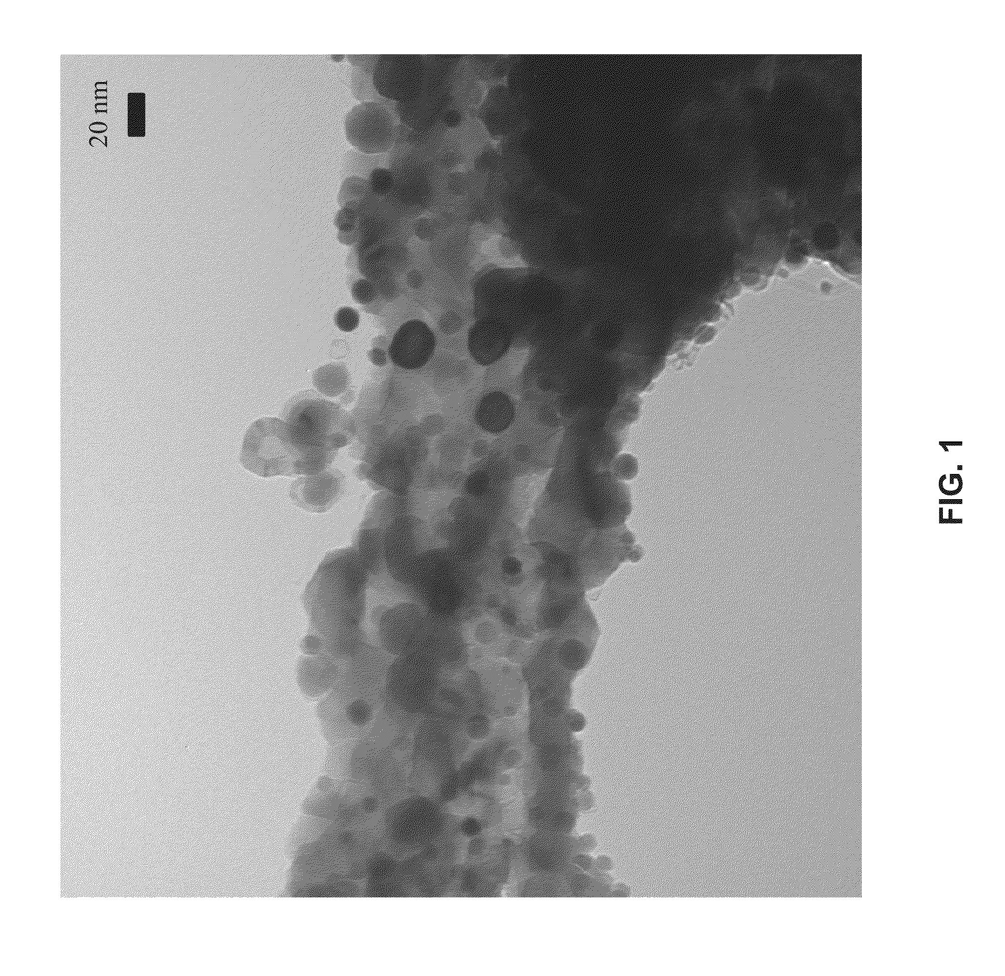
[0051]Large, high surface area, large pore size with interconnected pore poly(styrene-divinylbenzene; PS-DVB) polymer particles (Cavilink™, ˜600 μm, 43.5 m2 / g) have been coated via atomic layer deposition (ALD) with 50 layers of alumina resulting in a 15 nm alumina film. A fluidized bed reactor was used to apply all of the coatings, w...


PUM

PropertyMeasurementUnit
Temperatureaaaaaaaaaa

Abstract

A method and apparatus for gas-phase reduction/oxidation is disclosed. The apparatus includes a reactor including at least one reactor tube or containment vessel with active redox material within the reactor tube or containment vessel, a first reactant gas or vacuum for reducing the active redox material, and a second reactant gas for oxidizing the active redox material. The method may be run under substantially isothermal conditions and/or energy supplied to the apparatus may include solar energy, which may be concentrated.

Description

CROSS REFERENCE TO RELATED APPLICATIONS[0001]This application claims the benefit of provisional application No. 61 / 620,891, entitled METHOD AND APPARATUS FOR GAS-PHASE REDUCTION / OXIDATION PROCESS, and filed Apr. 5, 2012, the contents of which are incorporated herein by reference to the extent such contents do not conflict with the present disclosure.FIELD OF INVENTION[0002]The present invention generally relates to reduction / oxidation (redox) methods and apparatus. More particularly, the invention relates to substantially isothermal redox processes to split gas-phase reactants and to solar thermochemical reactor technology for effecting redox reactions.BACKGROUND OF THE INVENTION[0003]Various redox processes can be used to split gas-phase reactants. For example, hercynite, ceria, and M-ferrite redox cycles may be used to split water (vapors) and CO2. The hercynite cycle can be represented by the following equations.[0004]Hercynite cycle:Reduction: CoFe2O4+3Al2O3→CoAl2O4+2Fe2AlO4+½O2...

Claims


Application Information

Patent Timeline
IPC IPC(8): C01B3/06C01B31/18C01B32/40F24S20/20
CPCC01B3/061C01B31/18F24J2/07C01B13/0207Y02E60/364C01B3/045F24S20/20F24S70/225Y02E10/40Y02E60/36Y02P20/133
Inventor LICHTY, PAULMUHICH, CHRISTOPHERARIFIN, DARWINWEIMER, ALAN W.STEINFELD, ALDO
Owner UNIV OF COLORADO THE REGENTS OF
Why Eureka
Try Eureka