
Turn Signal Controlled Regenerative Braking And Decelerative Loading

a turn signal and regenerative braking technology, applied in the direction of external condition input parameters, driver input parameters, driver interactions, etc., can solve the problems of reducing the need to replace the brake system components, and the wear of the brake surface eventually, so as to reduce the use of friction braking, increase the overall propulsion efficiency of the hybrid electric vehicle, and reduce the effect of friction braking

Active Publication Date: 2013-10-10
PONZIANI RICHARD LOUIS
View PDF4 Cites 45 Cited by
  • Summary
  • Abstract
  • Description
  • Claims
  • Application Information

AI Technical Summary

Benefits of technology

The present invention improves the overall efficiency of hybrid electric vehicles and electric vehicles by increasing the use of regenerative braking and reducing friction braking. It also allows the driver to have greater control and optimize fuel economy by using the turn signal to slow down the vehicle before a turn. The system is designed to engage and disengage friction brakes based on the driver's habits and driving conditions. It can be integrated into existing vehicles without adding much cost and is designed to improve the driver's experience and vehicle performance. The invention also allows the driver to activate the turn signal multiple times in a single turn cycle event to further optimize the efficiency of the vehicle.

Problems solved by technology

Not only is this heat energy dissipated through the components of the vehicle and eventually to the atmosphere, but brake frictional surfaces experience wear each time the brake is applied and with normal ongoing use.
The brake system components eventually will need to be replaced as they wear out and the more frequently the brakes are used and the greater the pressure applied, the sooner the components will wear out.
It should be noted there are other speed-reducing forces that will inherently slow down the vehicle that are always present when the vehicle is moving, including aerodynamic drag, rolling resistance of the tires, and internal friction of moving vehicle components and thus, these forces are not relevant to the discussion in this specification due to their ubiquitous and unavoidable presence.
These are active means of vehicle deceleration that require a conscious engagement from the driver and will then introduce a reverse torque load at the wheels, thus reducing the speed of the vehicle.
One method is for the driver shift the transmission to a lower selected gear which increases engine speed and the higher revving engine will slow the vehicle.
In a vehicle with a diesel engine that is so equipped, an exhaust brake may be engaged which introduces increased engine back pressure and thus will slow the vehicle.
Also in a diesel vehicle, a compression release engine brake can be engaged resulting in a slowing of the vehicle.
In a hybrid electric vehicle (HEV) or an electric vehicle (EV), regenerative braking can be engaged which will result in a slowing of the vehicle.
In the case of the HEV or EV, the manufacturer's design of the vehicle with respect to active means of deceleration, e.g. regenerative braking, presents a dilemma in terms of a design compromise.
Therefore, the dilemma for the manufacturer designing a HEV or EV is how to control coasting and how to control regenerative braking with a proper balance with respect to driver's controls and timely needs in particular driving situations.
With this type of throttle lift, the entire vehicle including the driver and any passengers will likely experience a very high rate of deceleration.
This also may compromise the drivability of the vehicle with frequent, sudden decelerations when the driver's foot is lifted off the throttle.
This design is prone to result in a jerky ride with aggressive fore and aft movements.
Also, throttle-position-induced rapid deceleration can create the situation whereby a rear end crash from a following driver is an ever-present risk, or the vehicle may experience instability.
While the second state maximizes overall efficiency by utilizing the coasting feature, a majority of drivers will not make the conscious effort to engage this second state, thereby missing the opportunity to optimize on a large population of these vehicles.
The driver must make a choice of one or more modes and this selectable approach does not allow the vehicle to be automatically adaptable to the situation.
This approach also misses the opportunity to optimize on a large population of vehicles.

Method used


Image

  • Turn Signal Controlled Regenerative Braking And Decelerative Loading
  • Turn Signal Controlled Regenerative Braking And Decelerative Loading
  • Turn Signal Controlled Regenerative Braking And Decelerative Loading

Examples


Embodiment Construction

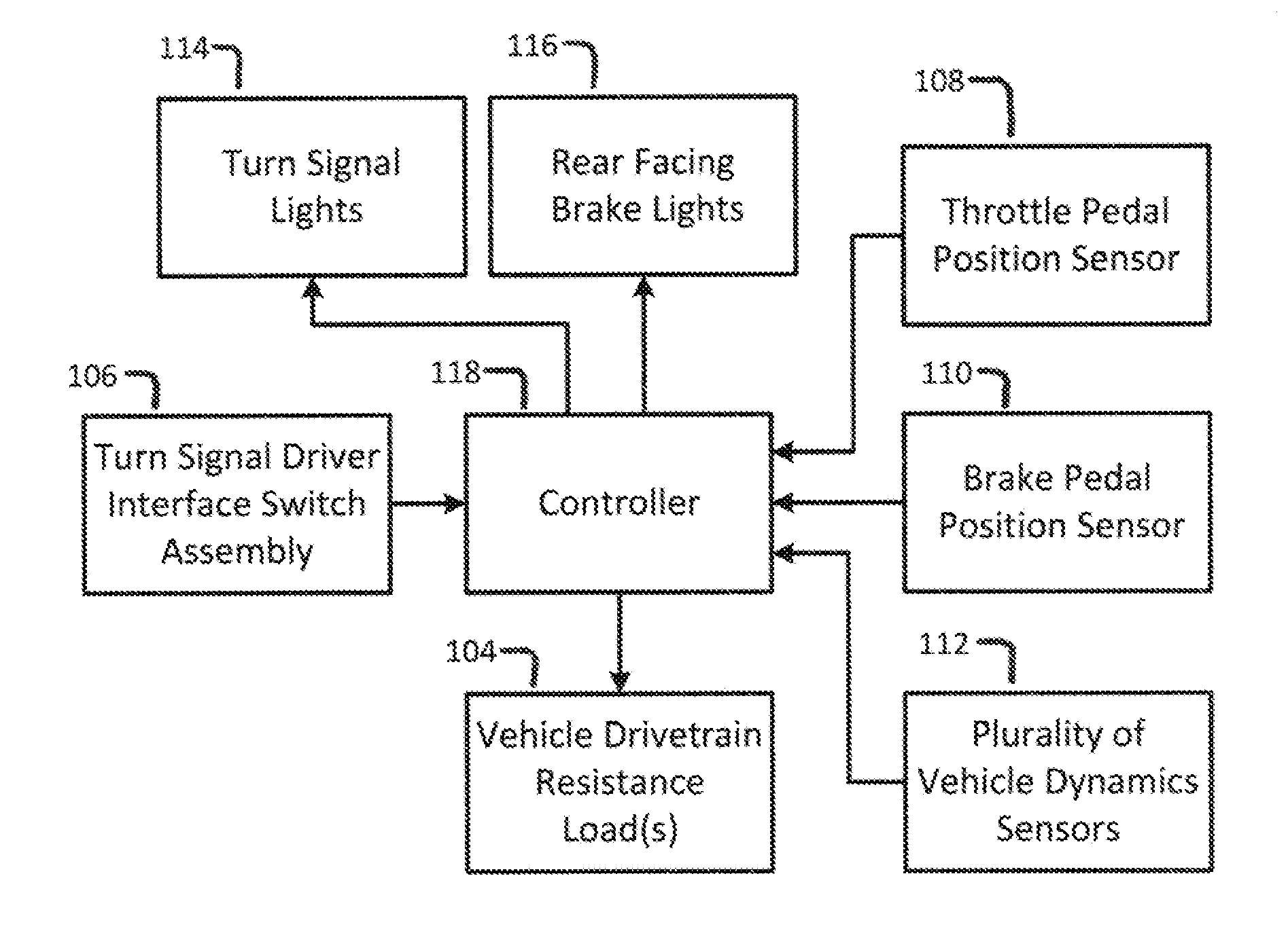
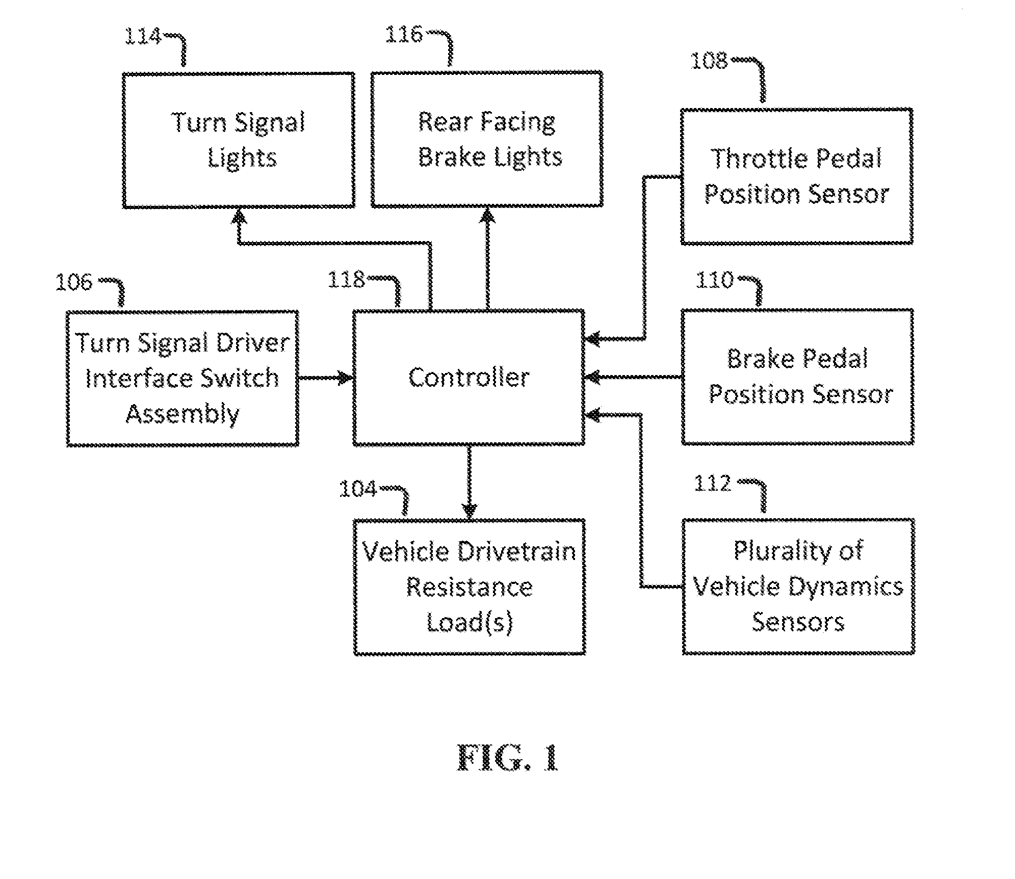
[0027]Referring now to the drawings, a vehicle drivetrain resistance load control system is illustrated in FIG. 1. A vehicle drivetrain resistance load is represented in Block 104 and would typically consist of one or more means of adding a negative torque load to the wheels of the vehicle i.e. a torque against the forward motion of the vehicle that would tend to slow down the vehicle. A vehicle is considered any wheeled vehicle designed to be driven upon the roadway. The load would typically be applied ultimately to the drive wheels against the roadway surface and would consist of all forms of regenerative braking and / or any other decelerative load that tends to slow down the vehicle by converting forward motion kinetic energy to other forms of energy. These forms would be one or more of many sources within the vehicle, some of which may include, but not limited to the following: An engine load, a transmission load, an electrical energy generator load, a hydraulic load, a frictiona...


PUM


Abstract

A vehicle executing a turn will most likely be slowed down before the turn and when a driver activates a turn signal to indicate the turn, a vehicle internal controller uses this information to engage regenerative braking for energy recapture while slowing down the vehicle for the pending turn. Since the turn signal is usually activated very early in the turn event, and turns are an ongoing, frequent part of driving, a greater overall vehicle efficiency can be realized without special effort from the driver. Implementation is relatively simple for the manufacturer and adds no cost since the controllers and sensors are already installed on nearly all roadworthy vehicles. Fuel mileage and vehicle driving ranges are improved on a large scale and brake system wear is reduced.

Description

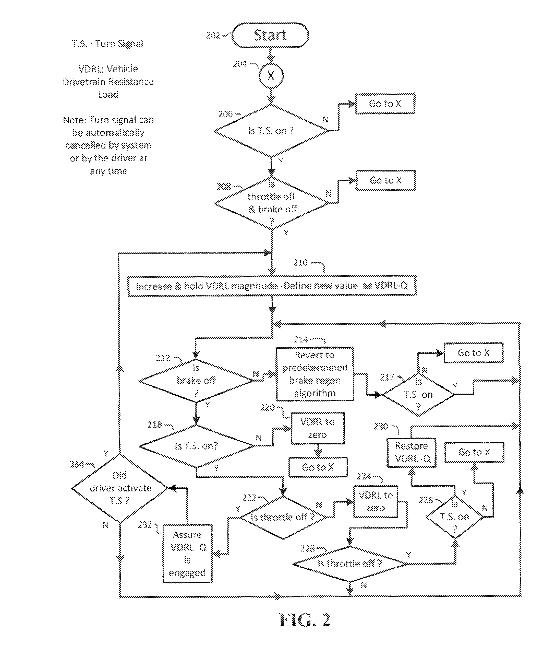
BACKGROUND OF THE INVENTION[0001]This invention relates in general to the control of vehicle regenerative braking and deceleration, using the turn signal activation status as input.[0002]As a normal course of driving a vehicle on public roadways, a driver directs the vehicle to a destination through a combination of straight travel and turns. Left and right turns of all kinds are just a normal, ongoing part of driving. As a vehicle on a roadway is approaching an intended turn and before the turn is executed, the driver will usually slow the vehicle from a normal driving speed to a lower speed that is appropriate to safely execute the turn. The execution of a turn therefore requires the driver to anticipate, plan, and act well before the actual turn is made. These steps usually consist of the following: Remove the foot from the throttle, and then apply the foot brake if necessary to achieve a lower speed, release the foot brake and then turn the steering wheel to execute the turn, an...

Claims


Application Information

Patent Timeline
IPC IPC(8): B60W30/00B60W10/30B60W10/18B60W10/04B60W10/10B60L50/15B60L50/16
CPCB60W30/00Y02T10/642B60W10/10B60W10/18B60W10/30B60W10/184B60W10/198B60W30/18109B60W30/18127B60W30/18136B60W2540/20B60W2710/0666B60W2710/083B60W2710/105B60W10/06B60W10/08B60W2030/18081B60W2550/402B60L7/12B60L7/26B60L11/123B60L11/14B60L11/1861B60L15/2009B60L2240/423B60L2240/443B60L2240/486B60L2240/622B60L2250/16B60L2250/26Y02T10/7077Y02T10/7044Y02T10/7005Y02T10/705Y02T90/16Y02T90/162Y02T10/7275Y02T10/6217Y02T10/7291B60W10/04B60Q1/44B60L50/61B60L50/16B60W2556/50Y02T10/62Y02T10/64Y02T10/70Y02T10/72Y02T10/7072
Inventor PONZIANI, RICHARD LOUIS
Owner PONZIANI RICHARD LOUIS
Learn More