Cryopump drain and vent

a cryopump and drain pipe technology, applied in the field of fast regeneration of cryopumps, can solve the problems of pressure spike and too small, and achieve the effect of maximum pressure and rapid melting

Active Publication Date: 2013-10-24
SUMITOMO SHI CRYOGENICS OF AMERICA
View PDF1 Cites 2 Cited by
  • Summary
  • Abstract
  • Description
  • Claims
  • Application Information

AI Technical Summary

Benefits of technology

[0011]The present invention applies to a means of rapidly melting a large quantity of type II cryogen in a cryopump that is configured to contain the liquid in the warm cryopanel with the inlet to the cryopump facing up or sideways, and venting the liquid and gas in a controlled way. Rapid melting is preferably accomplished by flowing a purge gas that will condense on the cryodeposit. By not allowing the liquid to drain onto the vacuum housing the evaporation rate is limited and the maximum pressure in the cryopump can be controlled by the purge gas flow rate.

Problems solved by technology

This chilling of one side of the vacuum housing can cause problems.
The main problem with this design is that the vent ports as described are too small to allow a high flow rate of venting gas which is necessary for a fast warm up of the cryopump.
This causes a spike in the pressure.

Method used


Image

  • Cryopump drain and vent
  • Cryopump drain and vent
  • Cryopump drain and vent

Examples


Embodiment Construction

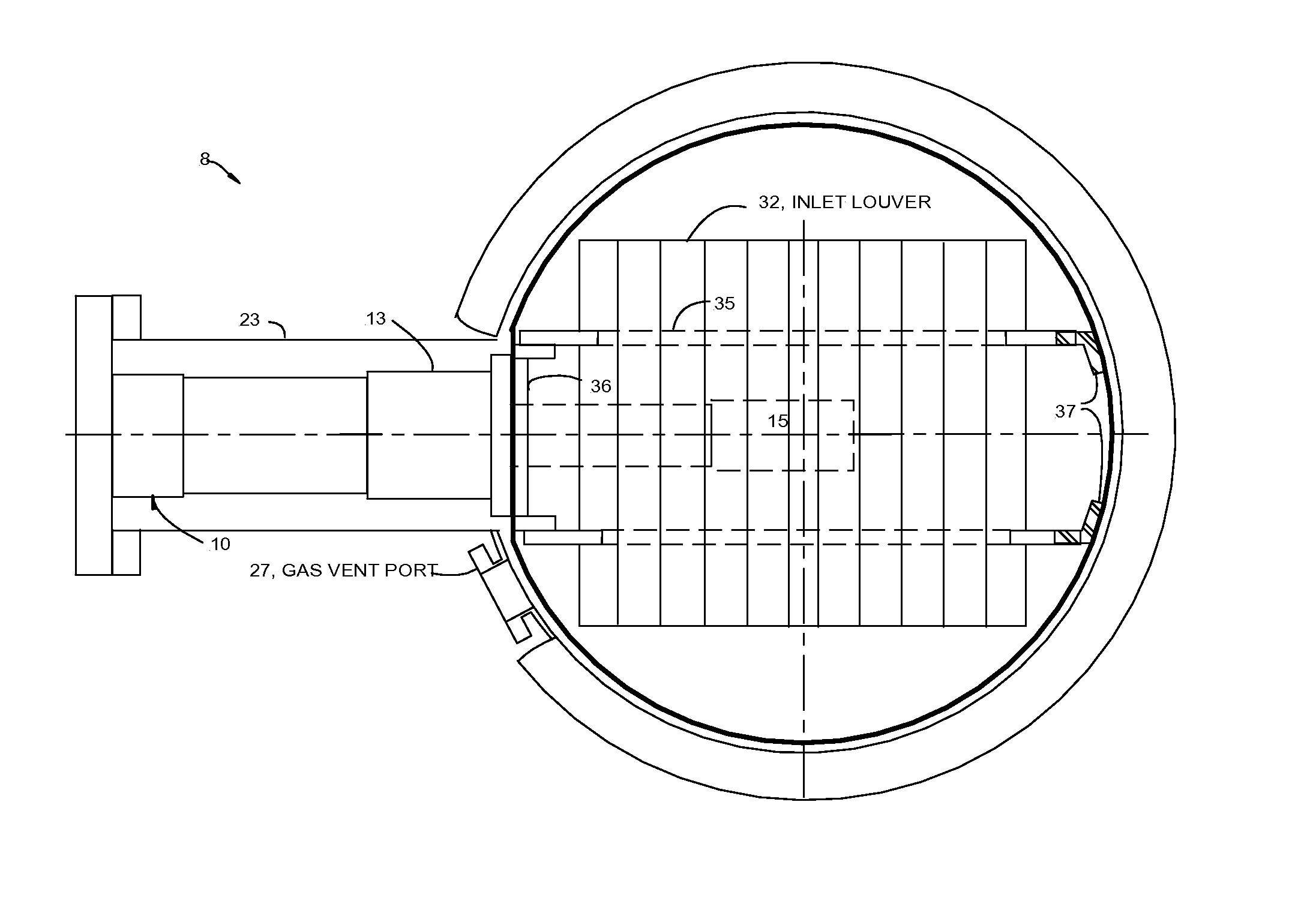
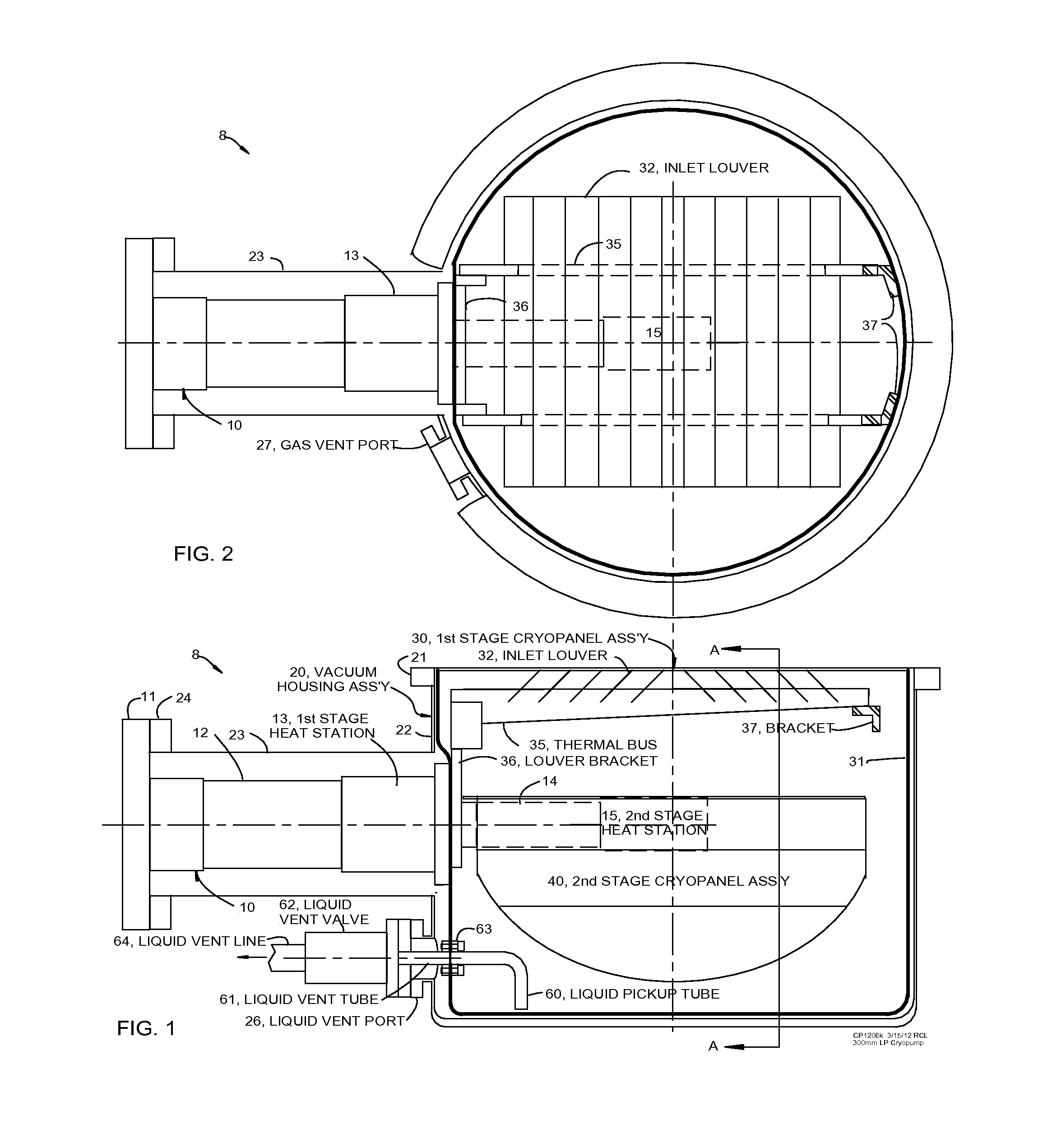
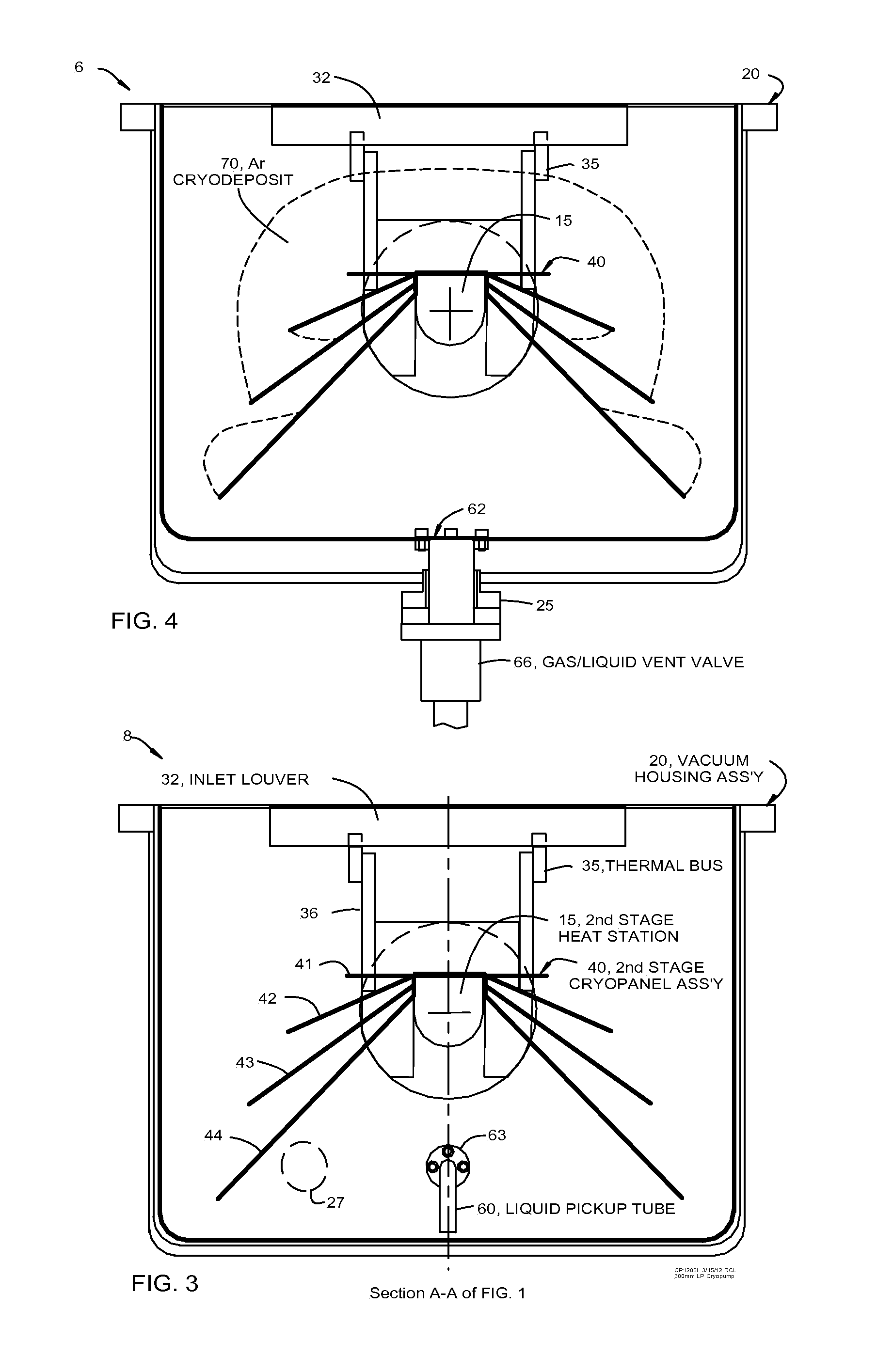
[0021]The side view cross section of low profile cryopump assembly 8 shown in FIG. 1 shows the main components including expander cylinder assembly 10, vacuum housing assembly 20, 1st stage cryopanel assembly 30, 2nd stage cryopanel assembly 40, and the liquid vent components. Expander cylinder assembly 10 consists of warm flange 11, 1st stage cylinder 12, 1st stage heat station 13, 2nd stage cylinder 14, and 2nd stage heat station 15. Vacuum housing assembly 20 consists of inlet mounting flange 21, cryopanel housing 22, cylinder housing 23, expander mounting flange 24, and liquid vent port 26. Not shown are mounting ports on cylinder housing 23 that are generally standard for cryopumps to mount a pressure gauge, temperature sensors, purge gas input, and an evacuation port. The 1st stage cryopanel assembly 30 consists of radiation shield 31 (frequently referred to as the warm panel), inlet louver 32, thermal bus 35, thermal bracket 36, and louver support bracket 37. The 2nd stage cr...


PUM

PropertyMeasurementUnit
pressureaaaaaaaaaa
sizeaaaaaaaaaa
weightaaaaaaaaaa

Abstract

A means of rapidly melting a large quantity of type II cryogen in a cryopump that is configured to contain the liquid in the warm cryopanel with the inlet to the cryopump facing up or sideways, and venting the liquid and gas in a controlled way. Rapid melting is preferably accomplished by flowing a purge gas that will condense on the cryodeposit. By not allowing the liquid to drain onto the vacuum housing the evaporation rate is limited and the maximum pressure in the cryopump can be controlled by the purge gas flow rate.

Description

BACKGROUND OF THE INVENTION[0001]The object of the present invention is to provide fast regeneration of a cryopump that is used for sputtering in the semi-conductor manufacturing process. Sputtering takes place with a flow of Ar at 100 to 200 scc / m for a period of about one minute, followed by a cessation of Ar flow while the pressure drops to a base pressure of less than 2*10−7 Torr and loading of a new wafer in about one minute. The throughput of semi-conductor wafers depends on a) fast recovery time to base pressure after flowing Ar, b) a lot of cycles between regenerations, and c) fast regeneration; consisting of fast warm up, fast removal of the cryodeposits, and fast cooldown. Since a cryopump removes the gaseous Ar by freezing it on the second stage (cold) cryopanel the pump has to be warmed up periodically (regenerated) to melt and remove the Ar cryodeposit, then cooled back to normal operating temperatures. Other gases such as water and hydrogen that accumulate in much smal...

Claims


Application Information

Patent Timeline
Patent Type & Authority Applications(United States)
IPC IPC(8): B01D8/00
CPCB01D8/00
Inventor LONGSWORTH, RALPH
Owner SUMITOMO SHI CRYOGENICS OF AMERICA
Why Eureka
Try Eureka