Inverter control system

a control system and sensor technology, applied in the direction of motor/generator/converter stopper, dynamo-electric converter control, dynamo-electric gear control, etc., can solve the problems of difficult to adopt, complicated wire circuit for connecting additional devices, and computing-capacity limit, so as to reduce the size, cost and loss, and the effect of low arithmetic load

Inactive Publication Date: 2013-10-24
MEIDENSHA ELECTRIC MFG CO LTD
View PDF1 Cites 8 Cited by
  • Summary
  • Abstract
  • Description
  • Claims
  • Application Information

AI Technical Summary

Benefits of technology

[0019]According to the present invention, an inverter control system can be provided

Problems solved by technology

Moreover, since the computing period becomes higher in speed as a motor rotational speed becomes higher, it is difficult to adopt the above-mentioned method (the motor current control and the sensorless method) in a control for ultra-high-speed motor (having hundreds of thousands of rotations min−1).
A bottleneck of this problem is a computing-capacity limit of an arithmetic unit (computing unit) relative to the control method.
Further, a wire circuit for conne

Method used


Image

  • Inverter control system
  • Inverter control system
  • Inverter control system

Examples


first embodiment

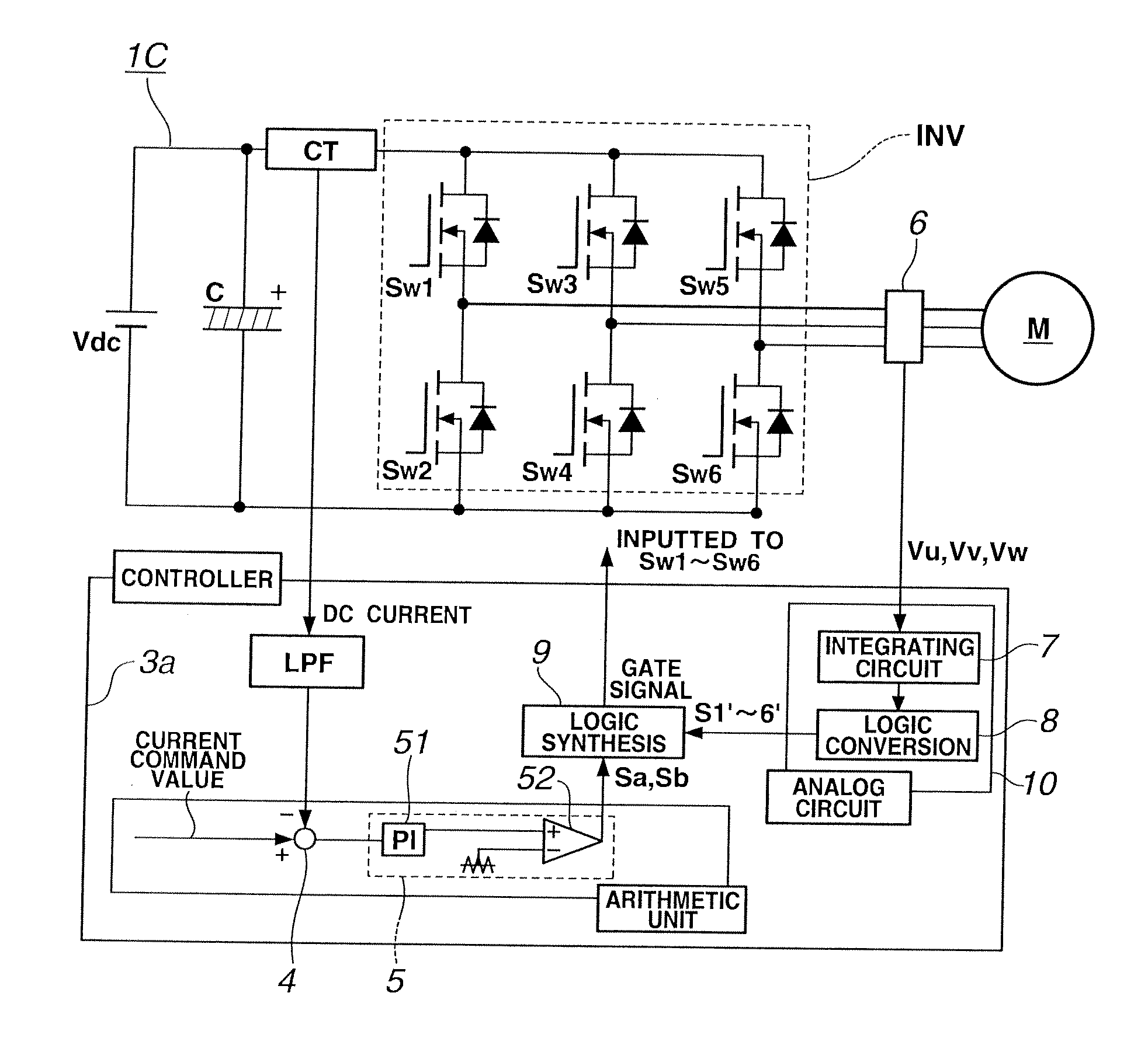
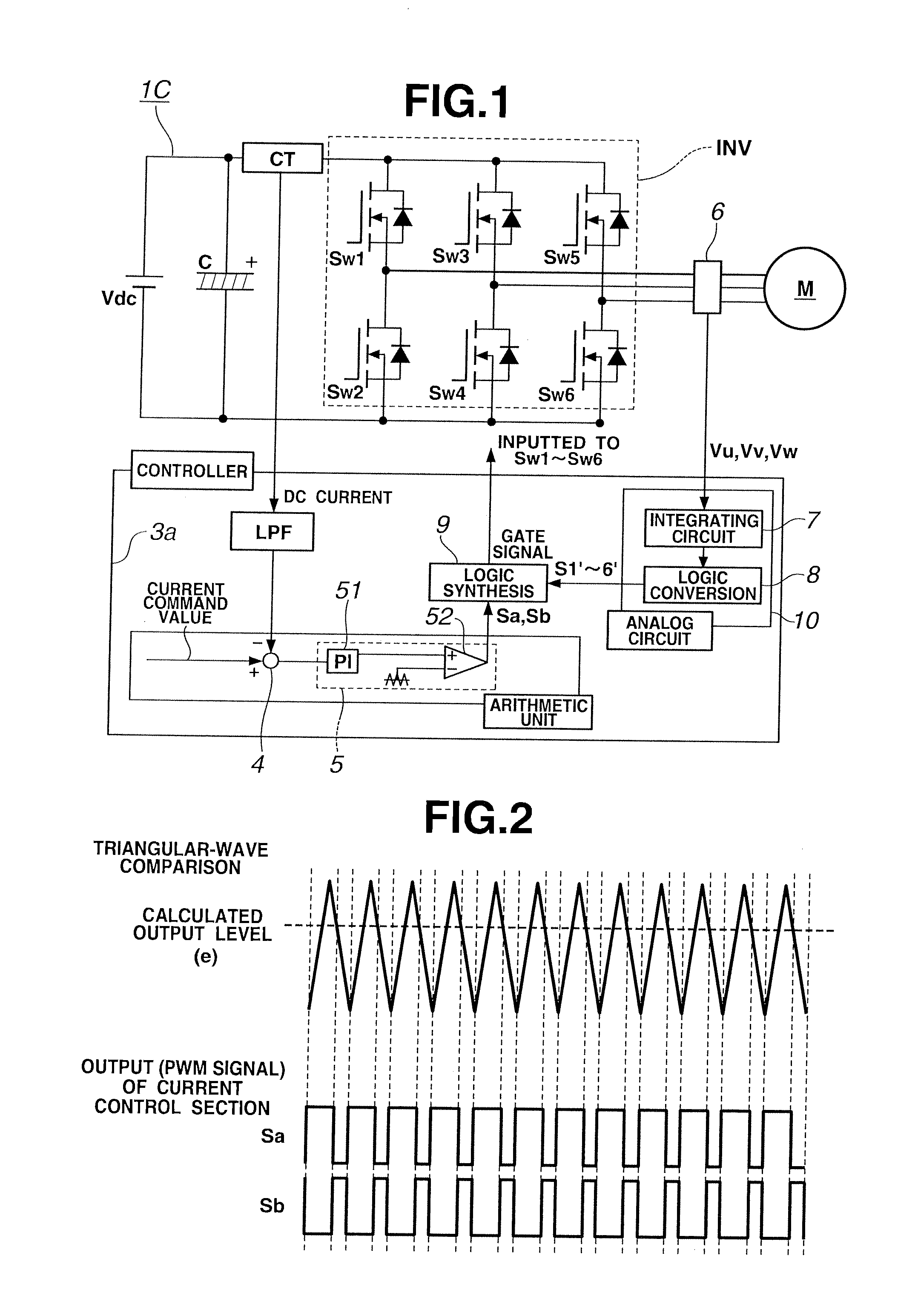
[0029]An inverter control system in a first embodiment according to the present invention will now be explained referring to FIGS. 1 to 4. The inverter control system in the first embodiment includes a main circuit 1C and a current-control controller 3a.

[0030]As shown in FIG. 1, the main circuit 1C in the first embodiment is constructed in the same manner as a general voltage-source PWM (pulse-width-modulation) inverter, and includes an inverter INV having a three-phase and six-element circuit. In this embodiment, a controlled object (i.e., a variable which is mainly used for the control) is an electric-current which is inputted to the inverter INV. Direct current (the input current of inverter) between a smoothing condenser C and switching elements Sw1 to Sw6 (i.e., between the smoothing condenser C and the inverter INV) is detected or obtained by a current sensor CT or the like. As the current sensor CT, any component that can detect or obtain the current value is able to be empl...

second embodiment

[0042]FIG. 5 is a block diagram showing a speed-control controller of an inverter control system in a second embodiment according to the present invention. Parts which are constructed in the same manner as the first embodiment are given same reference signs as those in the first embodiment, and the detailed explanations thereof will be omitted.

[0043]A structure of a main circuit in the second embodiment is the same as that of first embodiment. The inverter control system in the second embodiment includes the speed-control controller 3b in place of the current-control controller 3a of the first embodiment. Moreover, the input command in the second embodiment is a speed command value.

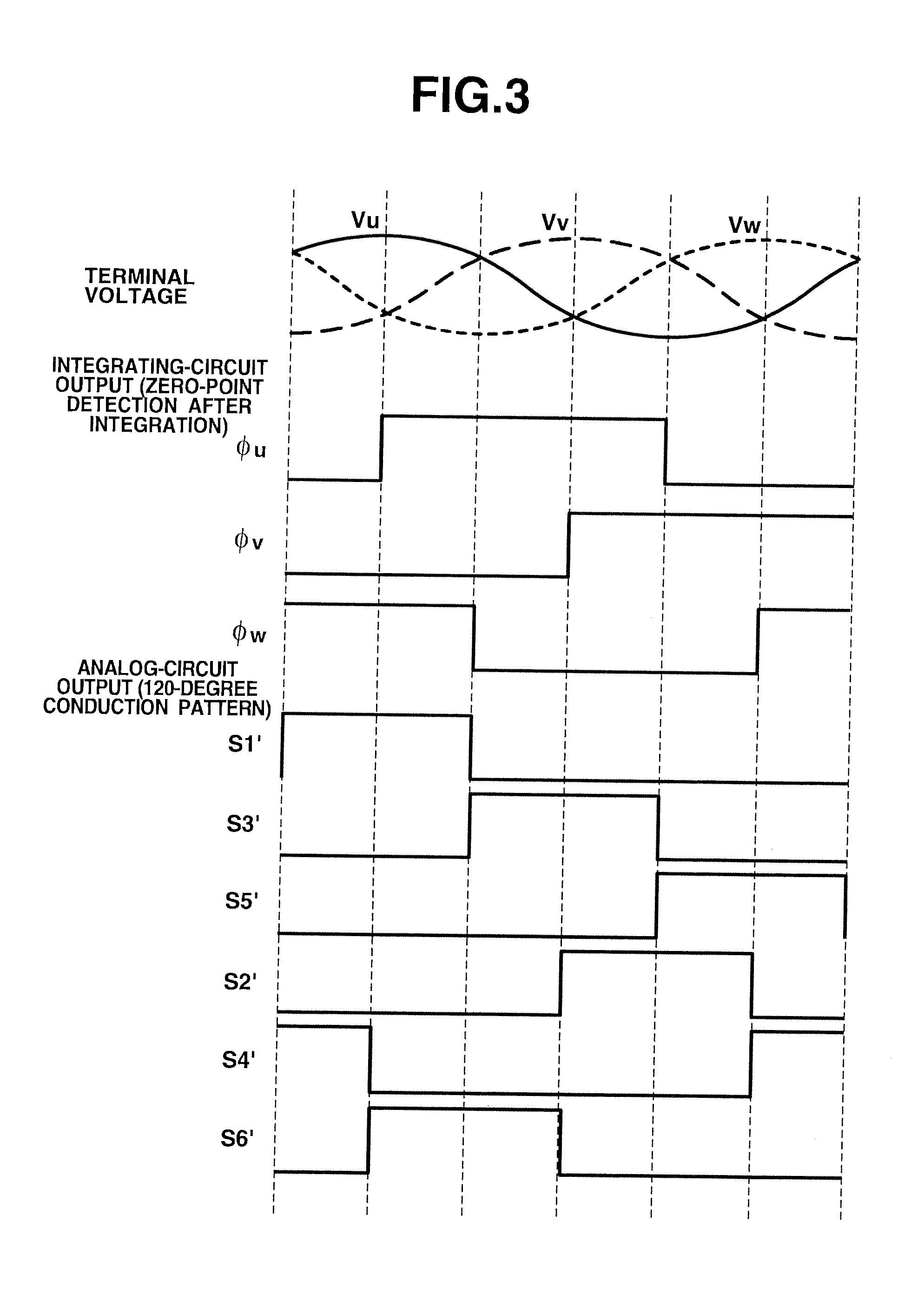
[0044]In the second embodiment, the 120-degree conduction patterns S1′ to S6′ outputted from the sensorless circuit 10 are converted into a speed detection value by a speed detector 11.

[0045]Next, a subtracting section 12 calculates a speed difference (deviation) between the speed detection value and the ...

third embodiment

[0047]FIG. 6 is a block diagram showing an electric-power-control controller of an inverter control system in a third embodiment according to the present invention. Parts which are constructed in the same manner as the first embodiment are given same reference signs as those in the first embodiment, and the detailed explanations thereof will be omitted.

[0048]A structure of a main circuit in the third embodiment is the same as that of first embodiment. The inverter control system in the third embodiment includes the electric-power-control controller 3c in place of the current-control controller 3a of the first embodiment. Moreover, the input command in the third embodiment is an electric-power command value.

[0049]In the third embodiment, DC voltage value (a voltage between both ends of the smoothing condenser C, i.e., an input voltage to the inverter) is detected. An electric-power detector 14 multiplies this voltage detection value by the DC component of the current detection value ...


PUM


Abstract

A LPF extracts DC component of a current detection value of an inverter input current. A subtracting section 4 calculates a difference between a current command value and the DC component of the current detection value. A current controller 5 produces two-phase PWM signals Sa and Sb complementary to each other, from the current difference. Further, an integrating circuit 7 integrates output terminal voltages Vu, Vv and Vw of the inverter to convert the output terminal voltages Vu, Vv and Vw into a magnetic-flux information Φu, Φv and Φw. A logic conversion section 8 converts the magnetic-flux information Φu, Φv and Φw into 120-degree conduction patterns S1′-S6′ to output the 120-degree conduction patterns S1′-S6′. Then, a logic circuit section 9 executes a logic synthesis between the PWM signals Sa and Sb and the 120-degree conduction patterns S1′-S6′ to output gate signals S1-S6.

Description

TECHNICAL FIELD[0001]The present invention relates to a sensorless control and a control system for 120-degree-conduction-type PWM inverter.BACKGROUND ART[0002]Generally, a voltage-source PWM method is used as an inverter control for driving a PM motor. In many cases, a vector control is applied to a current control of the motor, for the purpose of controlling a current waveform into a sine wave and thereby suppressing harmonics resulting in enabling a smooth control of the PM motor.[0003]Moreover, in many cases, a sensorless method is used for detecting a magnetic-pole position of the PM motor. In this sensorless method, in general, a terminal voltage of the motor is taken into a CPU by analog-digital conversion and the like so that the magnetic-pole position is detected.[0004]The motor current control and the sensorless method require a high arithmetic load (computational load) of the CPU, and hence, a computing period (cycle) needs to be sufficiently high-speed with respect to a ...

Claims


Application Information

Patent Timeline
IPC IPC(8): H02P21/00H02P6/06H02P6/08H02P6/16H02P6/182
CPCH02P21/0085H02M7/53875H02P27/08H02P2201/07H02P2205/01H02P6/182H02P23/0086
Inventor YAMAGUCHI, TAKASHIKAKEBAYASHI, TORU
Owner MEIDENSHA ELECTRIC MFG CO LTD
Why Eureka
Try Eureka