
Method And Device For Forming An Electrolyte Film On An Electrode Surface

a technology of electrolyte film and electrode surface, which is applied in the direction of electrode manufacturing process, instruments, coatings, etc., can solve the problems of inability to control the conductivity and composition of the electrolyte, the inability to form uniform films on a substrate comprising various materials, and the inability to form uniform films. , to achieve the effect of reducing surface tension, improving the formation of homogeneous films, and reducing energy consumption

Inactive Publication Date: 2013-10-24
AIRBUS OPERATIONS GMBH
View PDF7 Cites 4 Cited by
  • Summary
  • Abstract
  • Description
  • Claims
  • Application Information

AI Technical Summary

Benefits of technology

This patent describes a method for accurately and reproducibly examining the corrosion of different materials using a nonionic surfactant to improve the surface wettability and film thickness. The method also involves using a piezo-atomizer for efficient droplet distribution and a closed chamber to minimize external influences on the film thickness. A controllable fan is used to control the quantity of electrolyte mist. Overall, this patent provides a more precise and controlled approach for studying corrosion.

Problems solved by technology

In this environment the temperature of the outer skin of the fuselage structure is as low as approximately −55° C., so that the components subjected to ambient temperatures cool correspondingly, and on the inside of the structure condensate and ice form, with the result that different metallic materials that are interconnected in an electrically conductive manner are subject to galvanic corrosion in the presence of an aqueous phase.
This process is associated with a disadvantage in that the film formation cannot be controlled with respect to the conductivity and composition of the electrolyte.
The condensation behavior and the film formation are a function of the thermal conductivity of the substrate or of the substrate combination as well as of the surface texture, and for this reason it is difficult to form a uniform film on a substrate comprising various materials.
Furthermore, as is the case in the above-mentioned method, uncontrollable evaporation effects will occur.

Method used


Image

  • Method And Device For Forming An Electrolyte Film On An Electrode Surface
  • Method And Device For Forming An Electrolyte Film On An Electrode Surface

Examples


Embodiment Construction

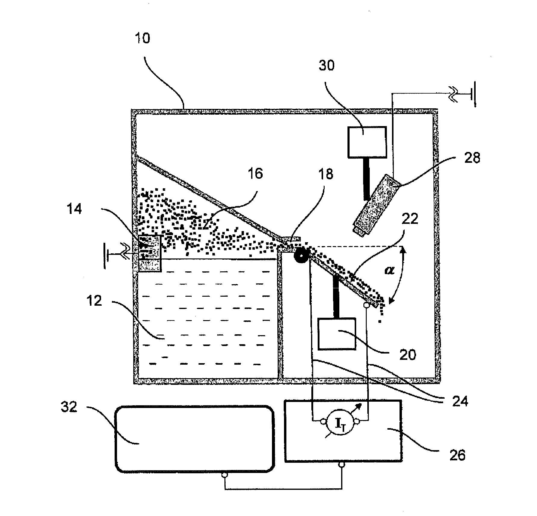
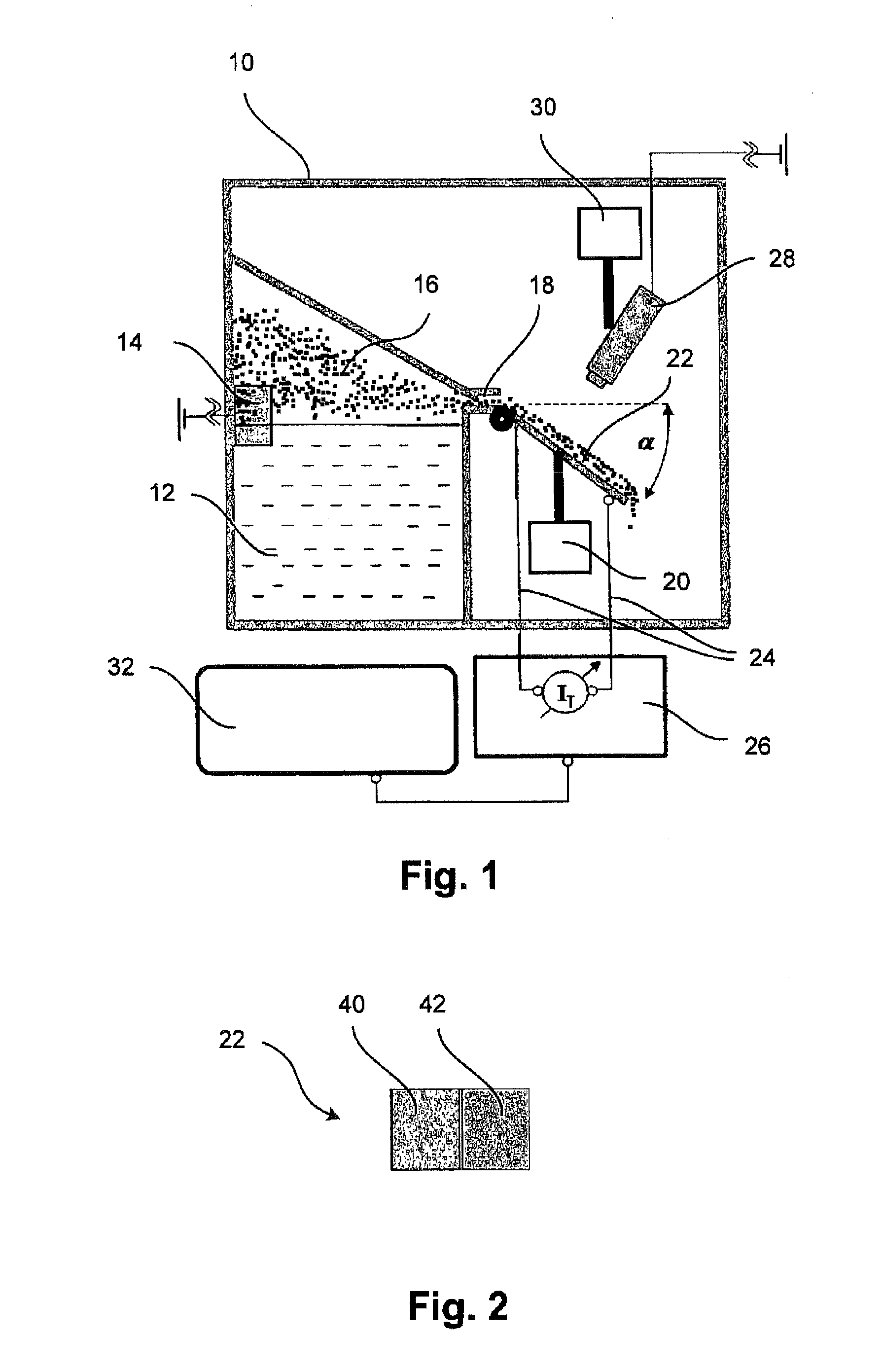
[0028]FIG. 1 shows a hermetically sealable chamber 10 in which an electrolyte reservoir 12 is arranged that contains an electrolyte, for example 0.1 mol / l sodium chloride. An atomizer 14, preferably designed as a piezo-atomizer, is used to atomize electrolyte from the electrolyte reservoir 12 in micro-droplets in a size of approximately 0.5-6 μm, which micro-droplets collect in the mist chamber 16. The mist chamber 16 comprises a mist outlet 18 that preferably comprises an adjustable cross section in order to control the quantity of the issuing electrolyte mist.

[0029]Furthermore, a substrate holder 20 is provided on which the substrate 22 is affixed, wherein the angle of inclination a of the substrate relative to the horizontal is variable. The substrate 22 is described in more detail in FIG. 2 and comprises at least two co-planar surfaces of different materials, which both act as electrodes. By means of connecting lines 24, all the electrodes are connected to a current-measuring de...


PUM

PropertyMeasurementUnit
angleaaaaaaaaaa
angleaaaaaaaaaa
temperaturesaaaaaaaaaa

Abstract

In a method for forming an electrolyte film on an electrode surface, the liquid electrolyte is sprayed into a cavity to form an electrolyte mist; the electrolyte mist exits the cavity through an opening and then flows across the electrode surface, which is directed downward at an angle behind the opening, whereby an electrolyte film is formed on the electrode surface and wherein the thickness of the electrolyte film is set by means of the angle of inclination of the electrode surface. A corresponding device includes an electrolyte tank communicating with a mist chamber for accommodating sprayed electrolyte by means of a spraying apparatus, wherein the mist chamber comprises a mist outlet. Furthermore, a retainer for fixing the electrode surface at a specifiable angle of inclination is provided, so that electrolyte mist, which can exit through the mist outlet, flows across the electrode surface to form an electrolyte film.

Description

CROSS-REFERENCE TO RELATED APPLICATIONS[0001]The present application is a continuation of International Application No. PCT / DE2011 / 002083, filed Dec. 7, 2011, which claims priority from German Patent Application No. 10 2010 055 042.6, filed Dec. 17, 2010, the disclosures of which are incorporated herein by reference.FIELD OF THE INVENTION[0002]The invention relates to a method and a device for forming an electrolyte film on an electrode surface. Such a method or such a device is used to examine the galvanic corrosion between different metallic materials under different conditions.BACKGROUND OF THE INVENTION[0003]Atmospheric corrosion phenomena under thin electrolyte films occur predominantly in the interior of aircraft during certain phases of flight or after landing. In this environment the temperature of the outer skin of the fuselage structure is as low as approximately −55° C., so that the components subjected to ambient temperatures cool correspondingly, and on the inside of th...

Claims


Application Information

Patent Timeline
Patent Type & Authority Applications(United States)
IPC IPC(8): H01M4/04
CPCH01M4/0407B05B7/0012B05B12/084B05B13/0228B05B17/0615G01N17/02Y02E60/10B05C5/02
Inventor HACK, THEOPALANI, SIVA
Owner AIRBUS OPERATIONS GMBH
Learn More