Method for UV based silylation chamber clean

a technology of optical components and cleaning methods, applied in chemical vapor deposition coatings, coatings, chemistry apparatuses and processes, etc., can solve the problems of significant tool downtime, affecting the efficiency of uv source cleaning, and reducing throughput correspondingly, so as to achieve efficient cleaning

Inactive Publication Date: 2013-10-31
APPLIED MATERIALS INC
View PDF0 Cites 16 Cited by
  • Summary
  • Abstract
  • Description
  • Claims
  • Application Information

AI Technical Summary

Benefits of technology

[0010]Embodiments of the invention generally provide methods for removing silylation residues on exposed surfaces of the chamber components (such as chamber walls, optical components, and substrate supp

Problems solved by technology

Because of the mechanical weakness, porous carbon-doped oxides are susceptible to damages caused by plasma etching and ashing processes that are known to lead to subsequent moisture uptake which detrimentally increase the dielectric constant to unacceptable levels.
During the silylation process, various exposed surfaces of the chamber components, such as the quartz based vacuum window, showerhead, and ch

Method used


Image

  • Method for UV based silylation chamber clean
  • Method for UV based silylation chamber clean
  • Method for UV based silylation chamber clean

Examples


Embodiment Construction

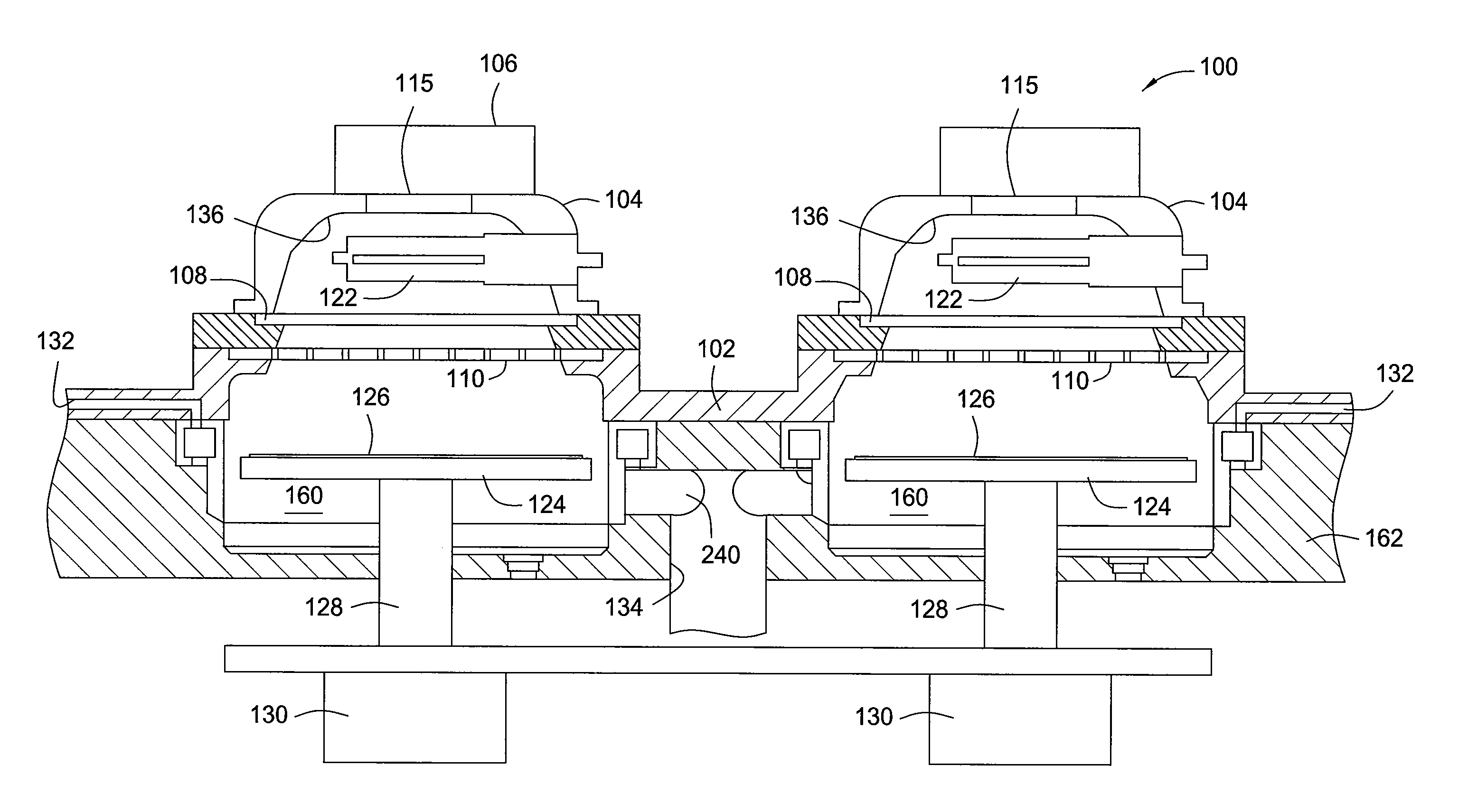
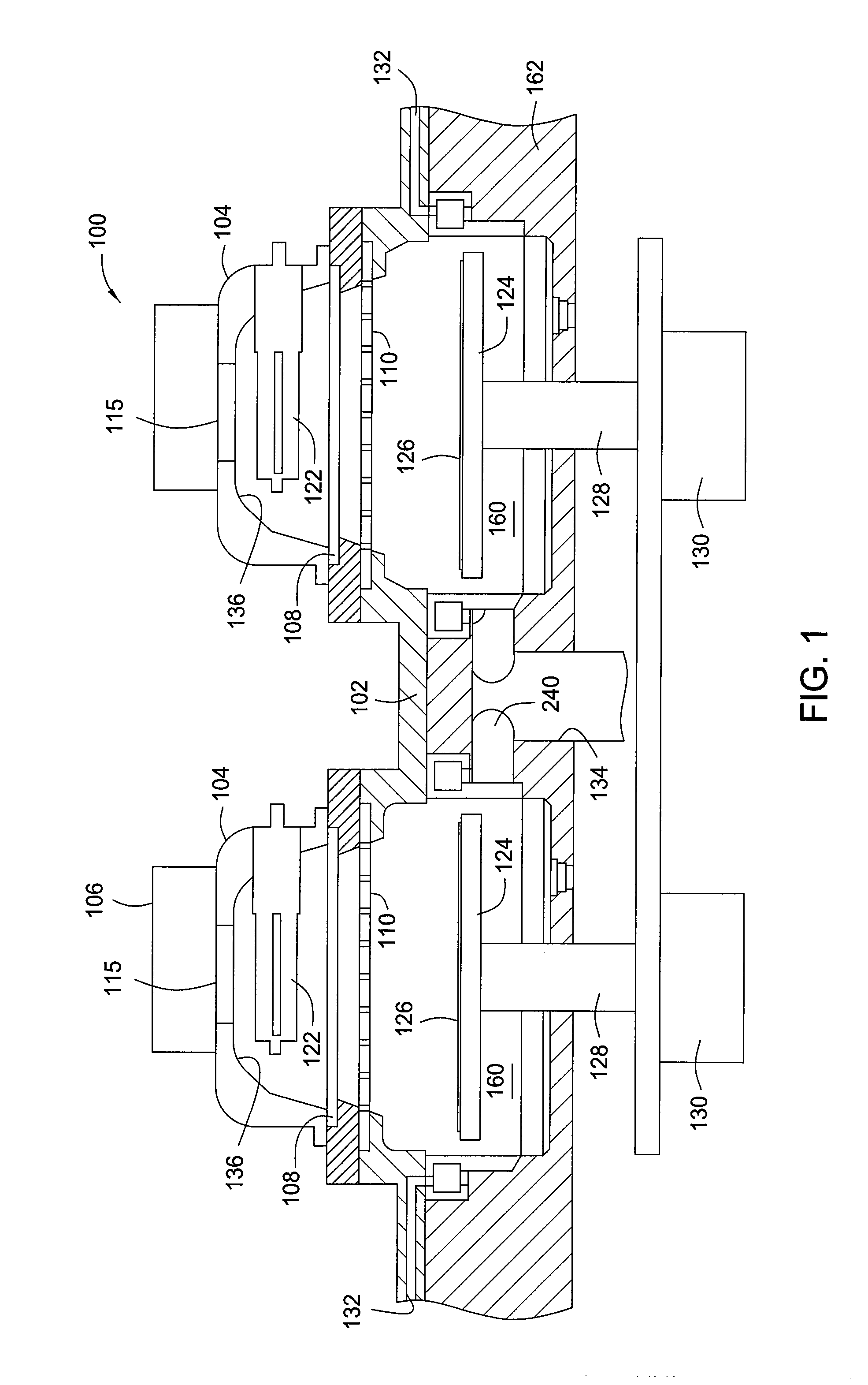
[0020]FIG. 1 illustrates a cross-sectional view of an exemplary tandem processing chamber 100 that benefits the present invention. The processing chamber 100 provides two separate and adjacent processing regions in a chamber body for processing the substrates. The processing chamber 100 has a lid 102, housings 104 and power sources 106. Each of the housings 104 cover a respective one of two UV lamp bulbs 122 disposed respectively above two processing regions 160 defined within the body 162. Each of the processing regions 160 includes a heating substrate support, such as substrate support 124, for supporting a substrate 126 within the processing regions 160. The UV lamp bulbs 122 emit UV light that is directed through the windows 108 and showerheads 110 onto each substrate located within each processing region. The substrate supports 124 can be made from ceramic or metal such as aluminum. The substrate supports 124 may couple to stems 128 that extend through a bottom of the body 162 ...


PUM

PropertyMeasurementUnit
Temperatureaaaaaaaaaa
Lengthaaaaaaaaaa

Abstract

Embodiments of the invention generally provide methods for cleaning a UV processing chamber. In one embodiment, the method includes flowing an oxygen-containing gas through a plurality of passages formed in a UV transparent gas distribution showerhead and into a processing region located between the UV transparent gas distribution showerhead and a substrate support disposed within the thermal processing chamber, exposing the oxygen-containing gas to UV radiation under a pressure scheme comprising a low pressure stage and a high pressure stage to generate reactive oxygen radicals, and removing unwanted residues or deposition build-up from exposed surfaces of chamber components presented in the thermal processing chamber using the reactive oxygen radicals.

Description

CROSS-REFERENCE TO RELATED APPLICATIONS[0001]This application claims benefit of U.S. provisional patent application Ser. No. 61 / 638,421, filed Apr. 25, 2012, which is herein incorporated by reference.BACKGROUND OF THE INVENTION[0002]1. Field of the Invention[0003]Embodiments of the invention relate to methods for cleaning optical components within a processing chamber.[0004]2. Description of the Related Art[0005]Semiconductor devices include metal layers that are insulated from each other by dielectric layers. As device features shrink, reducing the distance between the metal layers and between metal lines on each layer, capacitance increases. To address this problem, new insulating materials that have a relatively low dielectric constant are being used in place of silicon dioxide to form the dielectric layer that separates the metal lines. An exemplary material that may be used to form such a low-k dielectric layer is porous carbon doped oxide (CDO). Using this material instead of ...

Claims


Application Information

Patent Timeline
IPC IPC(8): B08B7/00
CPCB08B7/0021B08B7/0035C23C16/4405H01J37/3244H01J37/32862
Inventor XIE, BODEMOS, ALEXANDROS T.HENDRICKSON, SCOTT A.BALUJA, SANJEEVROCHA-ALVAREZ, JUAN CARLOS
Owner APPLIED MATERIALS INC
Why Eureka
Try Eureka