Subsea Electrical System Having Subsea Penetrator with Integral Current Sensor

a technology of current sensor and subsea electrical system, which is applied in the direction of substation/switching arrangement casing, non-enclosed substation, substation, etc., can solve the problems of complex systems and high cost, and achieve the effect of facilitating the connection of subsea electrical distribution system components

Inactive Publication Date: 2013-10-31
SCHNEIDER ELECTRIC IND SAS
View PDF5 Cites 7 Cited by
  • Summary
  • Abstract
  • Description
  • Claims
  • Application Information

AI Technical Summary

Benefits of technology

[0008]A system and method for coupling electrical power subsea. The system comprises a subsea electrical distribution system having at least one modular circuit breaker assembly. The modular circuit breaker assembly is controlled by a control system that has a plurality of circuit breaker controls. Each circuit breaker is operable to be controlled by

Problems solved by technology

Subsea pumping and processing system are particularly suited for challenging environments, such as the deep sea and Arctic,

Method used


Image

  • Subsea Electrical System Having Subsea Penetrator with Integral Current Sensor
  • Subsea Electrical System Having Subsea Penetrator with Integral Current Sensor
  • Subsea Electrical System Having Subsea Penetrator with Integral Current Sensor

Examples


Embodiment Construction

[0031]One or more specific embodiments of the present invention will be described below. In an effort to provide a concise description of these embodiments, not all features of an actual implementation are described in the specification. It should be appreciated that in the development of any such actual implementation, as in any engineering or design project, numerous implementation-specific decisions must be made to achieve the developers' specific goals, such as compliance with system-related and business-related constraints, which may vary from one implementation to another. Moreover, it should be appreciated that such a development effort might be complex and time consuming, but would nevertheless be a routine undertaking of design, fabrication, and manufacture for those of ordinary skill in the art and having the benefit of this disclosure.

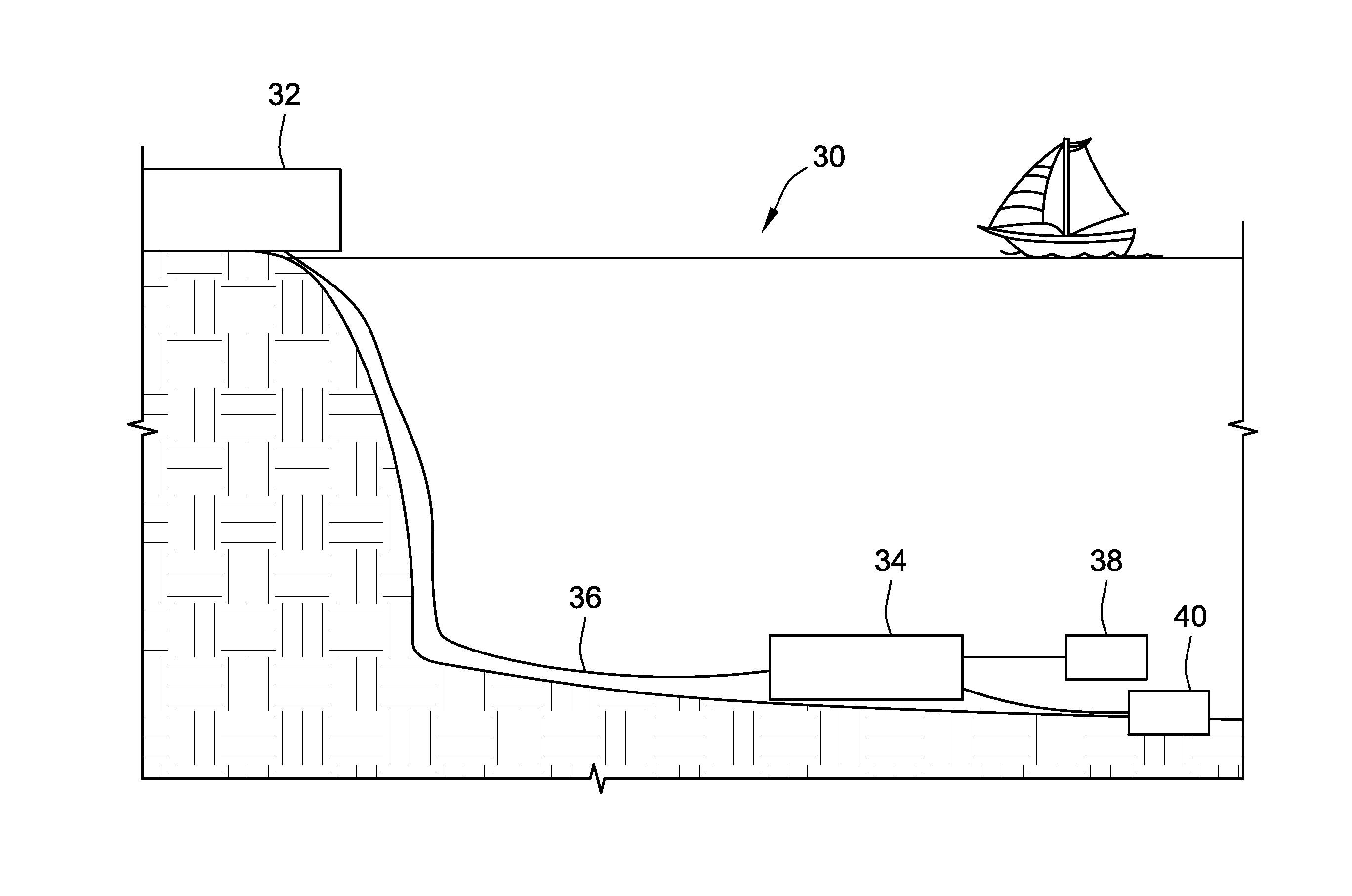
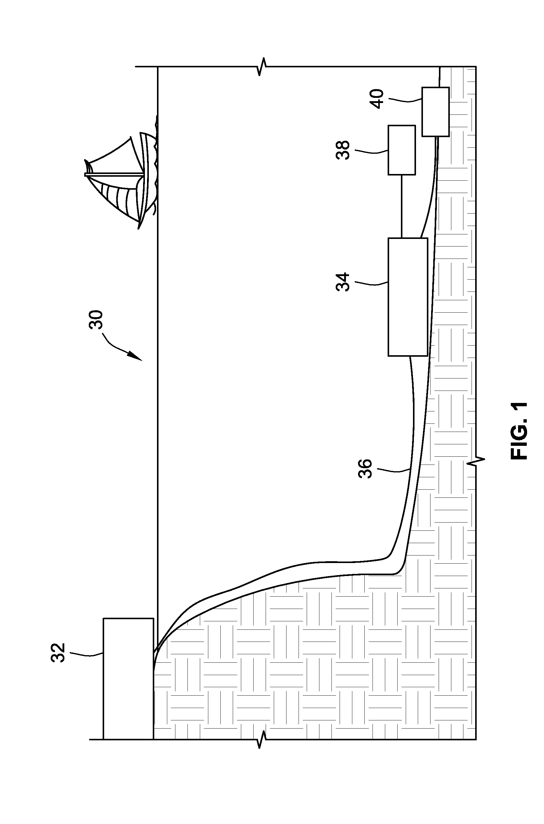
[0032]Referring generally to FIG. 1, a system for providing electric power subsea is presented and referenced generally by reference numera...


PUM

PropertyMeasurementUnit
Poweraaaaaaaaaa
Currentaaaaaaaaaa
Electrical conductoraaaaaaaaaa

Abstract

A system and method for coupling electrical power subsea. The system comprises a subsea penetrator to seal an opening around a conductor extending through a partition or enclosure. The subsea penetrator comprises an integral current sensor operable to produce a signal representative of current through the conductor. The penetrator comprises a boot configured to seal the opening through which the conductor extends. The current sensor may be disposed within the boot.

Description

CROSS-REFERENCE TO RELATED APPLICATIONS[0001]This application claims priority to Provisional patent application No. 61 / 639,865, filed on Apr. 28, 2012, which is hereby incorporated by reference in its entirety.BACKGROUND[0002]1. Field of the Invention[0003]The present invention relates generally to subsea electrical systems and, more specifically, to a subsea electrical distribution system comprising a subsea circuit breaker.[0004]2. Description of the Related Art[0005]This section is intended to introduce the reader to aspects of art that may be related to aspects of the present invention, which are described and / or claimed below. This discussion is believed to be helpful in providing the reader with background information to facilitate a better understanding of the various aspects of the present invention. Accordingly, it should be understood that these statements are to be read in this light, and not as admissions of prior art.[0006]The petroleum industry has seen an increase in ...

Claims


Application Information

Patent Timeline
IPC IPC(8): H02B7/00
CPCH02B7/00H02J3/36H02J4/00Y02E60/60H02J13/00019H02J2310/12H02J13/00017H02J13/00004H02J13/00034Y04S40/124Y10T29/49117Y10T29/49105Y02E60/00H05K7/14337H02B5/06H02B1/22H01H69/00H02B1/26H02B1/01
Inventor ANDREA, PIERRICKARRIVE, SERGE BERNARD YVES
Owner SCHNEIDER ELECTRIC IND SAS
Why Eureka
Try Eureka