Interfacing a Switch Array

Active Publication Date: 2013-10-31
TELEFON AB LM ERICSSON (PUBL)
View PDF0 Cites 2 Cited by
  • Summary
  • Abstract
  • Description
  • Claims
  • Application Information

AI Technical Summary

Benefits of technology

[0026]In another example, the threshold current magnitude of the threshold current may be equal to a magnitude of a scaled down version of the selected reference current. This enables reduced power consumption.
[0027]The current detector may comprise a counter for counting pulses of a clock signal and for controlling the selection means to select sequentially the different ones of the plurality of the one or more reference currents with sequentially increasing reference current magnitudes dependent on the count. Likewise, the method may comprise counting pulses of a clock signal and selecting sequentially the different ones of the plurality of the one or more reference currents with sequentially increasing reference current magnitudes dependent on the count. This enables a low complexity.
[0028]The current detector may be arranged to start the counter in response to detecting the switch array current flowing at any of the one or more column interface ports, and to stop the counter in response to detecting the threshold current having a smallest one of a plurality of the one or more threshold current magnitudes which exceeds the comparison current magnitude of the comparison current. Likewise, the method may comprise starting the counting in response to detecting the switch array current flowing at any of the one or more column conductors, and stopping the counting in response to detecting the threshold current having a smallest one of a plurality of the one or more threshold current magnitudes which exceeds the comparison current magnitude of the comparison current. This enables power consumption to be low, by operating the counter, or by counting, for only a period required to determine the magnitude of the switch array current.
[0029]The comparison means may comprise at least one current comparator comprising: a first comparator current mirror having a first comparator port for the threshold current and a second comparator port for a mirror of current at the first comparator port; a second comparator current mirror having a third comparator port for the comparison current and a fourth comparator port for a mirror of current at the third comparator port; a third comparator current mirror having a fifth comparator port coupled to the fourth comparator port and a sixth comparator port for a mirror of current at t

Problems solved by technology
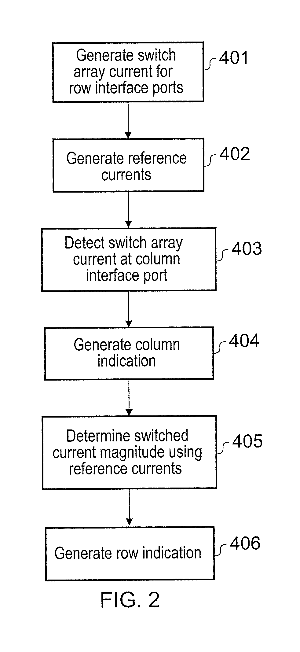
Elements having an output with a high voltage swing and a high frequency, such as an RF transmitter, a DC to DC converter or a class D audio amplifier, can cause electrical interference to elements having a sensitive RF input, or a sensitive analogue input, such as a microphone input or a high resolution analogue to digital converter.
However, even where a keyboard inte

Method used


Image

  • Interfacing a Switch Array
  • Interfacing a Switch Array
  • Interfacing a Switch Array

Examples


Embodiment Construction

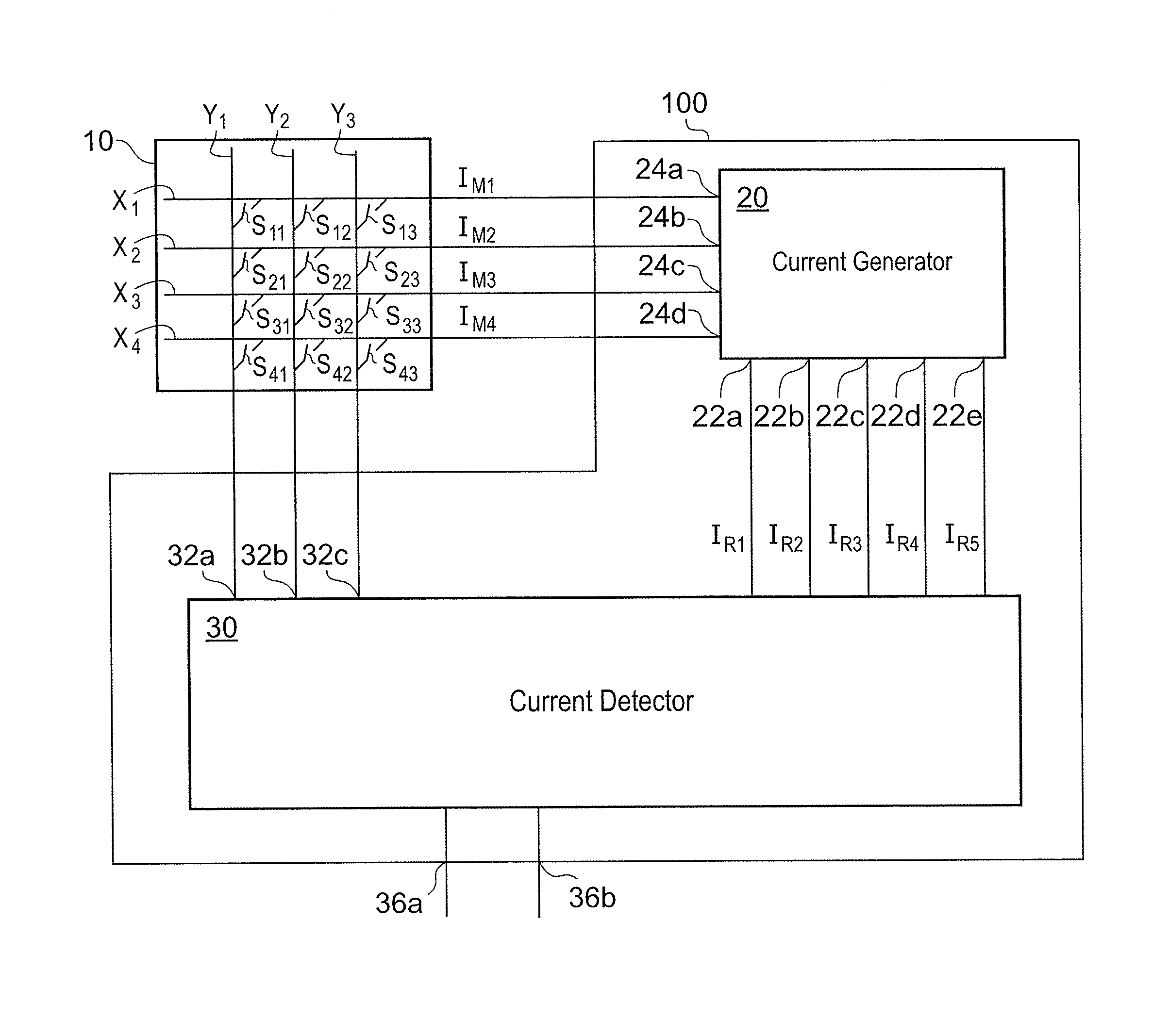
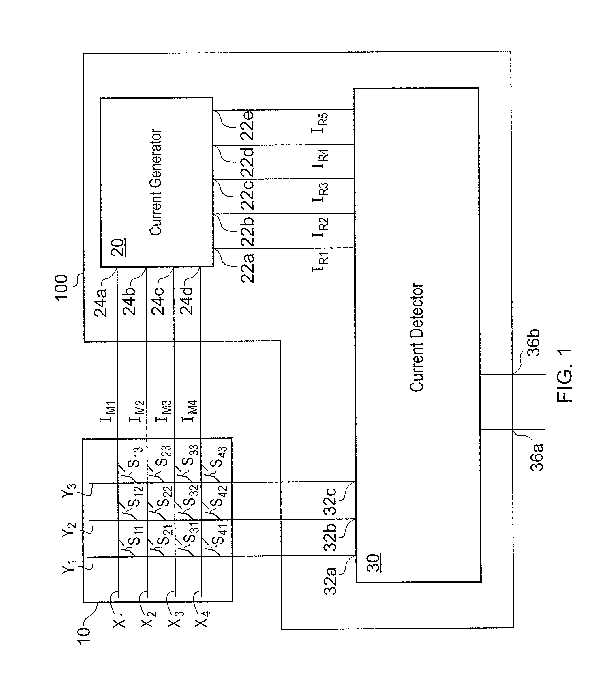
[0047]Referring to FIG. 1, an interface circuit 100 in accordance with a preferred embodiment of the present disclosure is coupled to a switch array 10 having an array of switches Sij, i=1 . . . 4, j=1 . . . 3. The switch array 10 has four row conductors X1 . . . X4 and three column conductors Y1 . . . Y3. Each of the switches Sij is coupled between one of the row conductors X1 . . . X4 and one of the column conductors Y1 . . . Y3. The switches Sij are normally non-conducting, and when activated, that is closed, provide a conduction path between the respective row conductor X1 . . . X4 and column conductor Y1 . . . Y3 to which they are coupled. Therefore, the array of switches Sij, i=1 . . . 4, j=1 . . . 3 is arranged as a matrix.

[0048]The interface circuit 100 comprises a current generator 20 and a current detector 30. The current generator 20 generates a switch array current IM for application to the switch array 10. The current generator 20 has row interface ports 24a . . . 24d w...


PUM


Abstract

An interface circuit for a switch array having an array of switches, each closeable to couple a row conductor of a plurality of row conductors to a column conductor of one or more column conductors, comprises a current generator and a current detector. The current generator has a plurality of row interface ports for coupling to different ones of the row conductors and is arranged to generate a switch array current for coupling to the row interface ports, the switch array current having a different one of a plurality of different switch array current magnitudes for different ones of the row interface ports, and generate one or more reference currents each having a different reference current magnitude. The current detector has one or more column interface ports for coupling to the one or more column conductors and is arranged to detect the switch array current flowing at any one of the one or more column interface ports, and generate a row indication indicative of which of the row conductors a closed one of the switches is coupled to by determining which one of the switch array current magnitudes the detected switch array current has by comparing the detected switch array current with the one or more reference currents.

Description

FIELD OF THE DISCLOSURE[0001]The present disclosure relates to an interface circuit for a switch array, for example for interfacing a keyboard to a processing device, and to a method of operating an interface circuit for a switch array.BACKGROUND TO THE DISCLOSURE[0002]There is an increasing requirement for a high level of integration of electronic circuits, particularly involving different types of circuitry such as RF circuits, analogue baseband circuits and digital circuits. For example, there is a requirement for a mobile telephone or a television receiver integrated in a single monolithic chip, or in a single package containing more than one chip, to contain circuitry for implementing at least some of the following elements: a fast memory interface, various digital interfaces such as a Universal Serial Bus (USB) and a Inter-Integrated Circuit (IIC) bus, a digital processing unit, analogue and mixed signal blocks, a radio frequency (RF) receiver and transmitter, a power manageme...

Claims


Application Information

Patent Timeline
IPC IPC(8): G06F13/38
CPCG06F13/385H04Q3/521H04Q2213/1302H04Q2213/1304H04Q2213/13213H04Q2213/13305
Inventor SLAVOV, NEDYALKO
Owner TELEFON AB LM ERICSSON (PUBL)
Why Eureka
Try Eureka