Fixed cutter drill bit with rotating cutter disc

a fixed cutter and drill bit technology, applied in the field of drill bits, can solve the problems of increasing wear and/or potential destruction of the cutting element and the drill bit body, drilling efficiency and accuracy, and reducing the life of the cutting elemen

Active Publication Date: 2013-11-07
ULTERRA DRILLING TECH LP
View PDF2 Cites 47 Cited by
  • Summary
  • Abstract
  • Description
  • Claims
  • Application Information

AI Technical Summary

Benefits of technology

[0014]A primary object of the invention is to provide a drill bit having prolonged life.

Problems solved by technology

However, conventional fixed cutter drill bits having conventionally attached cutting elements suffer from a number of drawbacks and disadvantages.
The constant engagement between this select portion of the cutting edge and the formation tends to quickly degrade and wear down the engaged portion of the cutting edge, resulting in decreased cutting element life, drilling efficiency, and accuracy.
This constant engagement also significantly increases the temperature of the cutting element, which may further result in increased wear and / or potential destruction of the cutting element and drill bit body.
This heat causes thermal damage to the PDC in the fowl of cracks which lead to spalling of the polycrystalline diamond layer, delamination between the polycrystalline diamond and substrate, and back conversion of the diamond to graphite causing rapid abrasive wear.
The high magnitude stresses at the critical region alone or in combination with other factors, such as residual thermal stresses, can result in the initiation and growth of cracks across the ultra-hard layer of the cutter.
Cracks of sufficient length may cause the separation of a sufficiently large piece of ultra-hard material, rendering the cutter ineffective or resulting in the failure of the cutter.
The high stresses, particularly shear stresses, may also result in delamination of the ultra-hard layer at the interface.
Bit designs in which one or more fixed cutters are individually rotatable are not an effective solution.
Further, it is very challenging to preserve the structural integrity of any small piece, such as an individual fixed cutter, under these extreme mechanical and thermal stresses.
Over time and / or when drilling certain hard but not necessarily highly abrasive rock formations, the edge of the working surface that constantly contacts the formation begins to wear down, forming a local wear flat, or an area worn disproportionately to the remainder of the cutting element.
Local wear flats may result in longer drilling times due to a reduced ability of the drill bit to effectively penetrate the work material and a loss of rate of penetration caused by dulling of edge of the cutting element.
That is, the worn cutter acts as a friction bearing surface that generates heat, which accelerates the wear of the cutter and slows the penetration rate of the drill.
Such flat surfaces effectively stop or severely reduce the rate of formation cutting because the conventional cutters are not able to adequately engage and efficiently remove the formation material from the area of contact.
The failure conditions described above require expensive and time-consuming repair measures.

Method used


Image

  • Fixed cutter drill bit with rotating cutter disc
  • Fixed cutter drill bit with rotating cutter disc
  • Fixed cutter drill bit with rotating cutter disc

Examples


Embodiment Construction

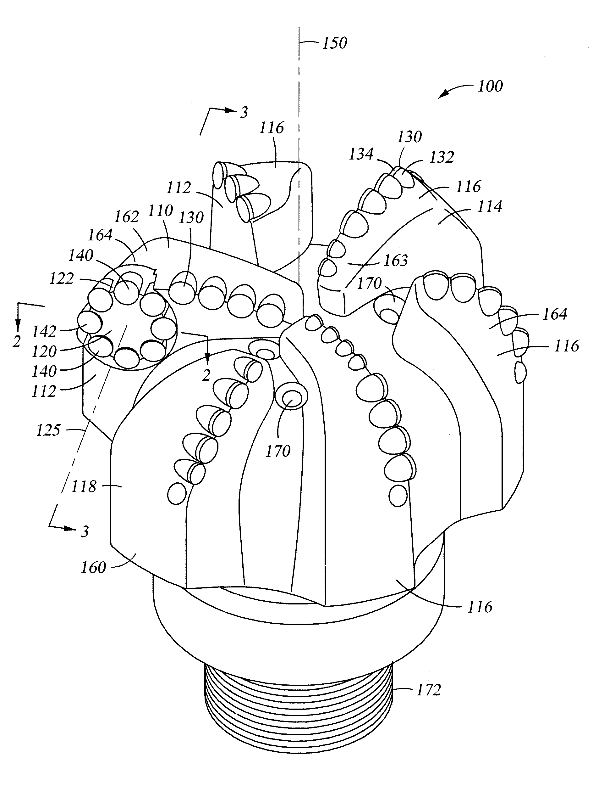
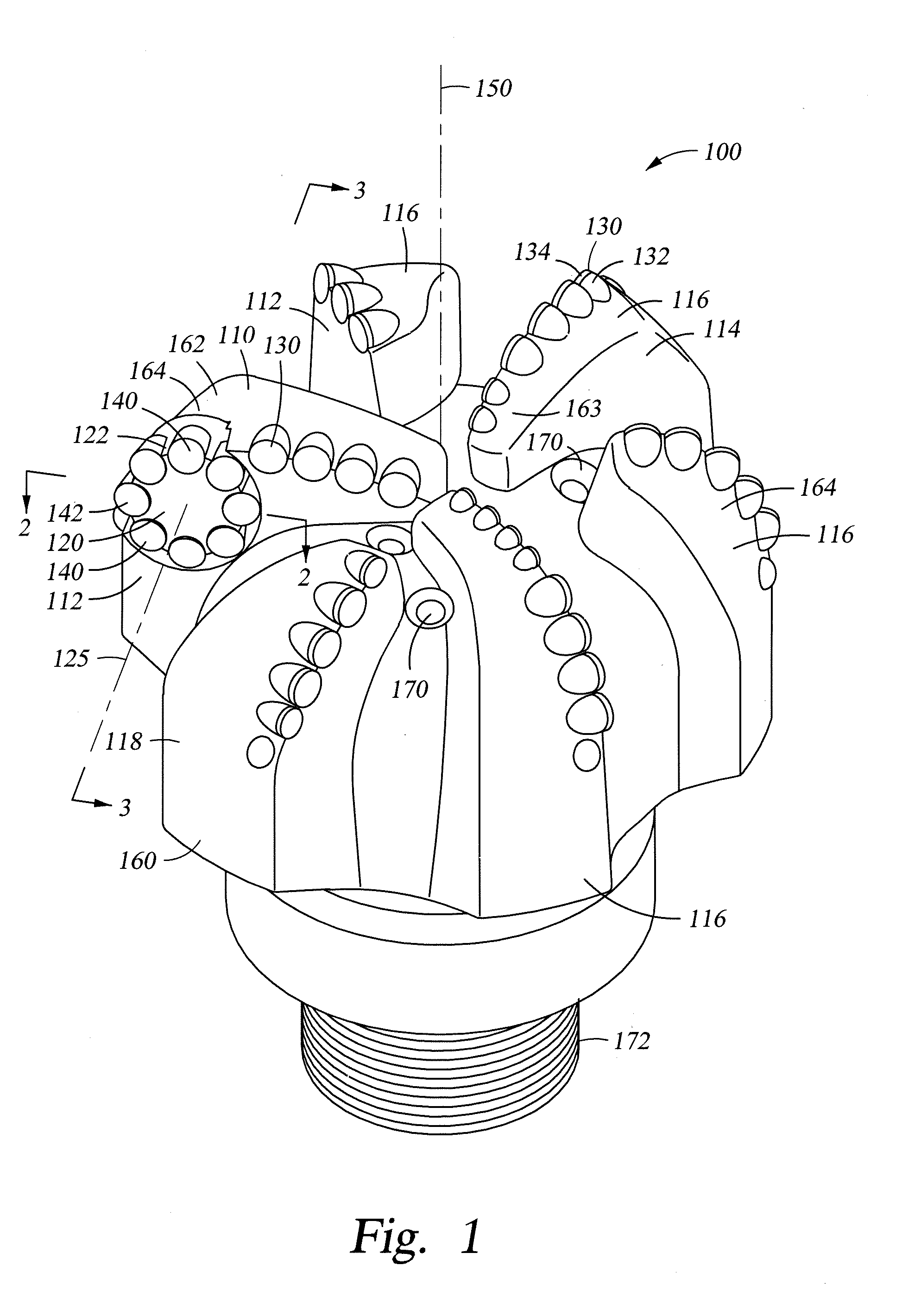
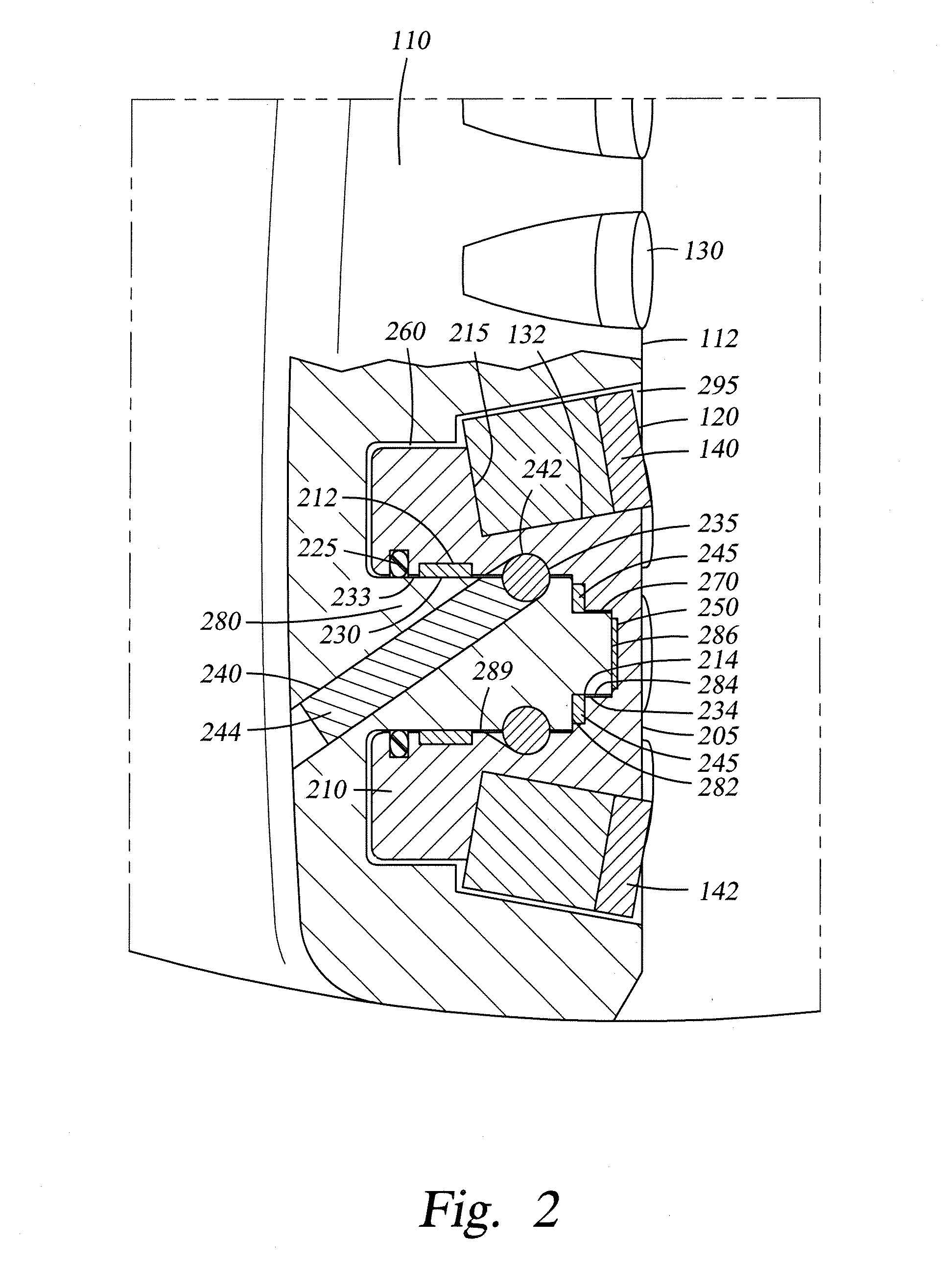
[0031]In one embodiment of this invention, one or more blades of a fixed cutter drill bit include an integrally-mounted rotating disc with cutters around the circumference of the disc. This disc is mounted to bearings to handle the torque generated and the weight on bit required to cut the formation. The angle the disc is mounted at will generate a torque on the disc causing it to rotate around. As it rotates around new cutters are presented to the formation. This disc could vary in size to cover the entire blade or just a certain portion of the blade, preferably the shoulder area of the bit profile where the cutters generally do most work. The exposure of the disc could also be set to enable it to rotate while under load, i.e. the cutters on the outside of the bit may contact the formation while the inner half of the disc is protected by a fixed blade.

[0032]FIG. 1 depicts an exemplary embodiment of a drill bit 100. Drill bit 100 generally represents any number of earth-boring or dr...


PUM


Abstract

A fixed cutter drill bit that includes one or more integrally-mounted rotating disc with cutters around the circumference of the disc. Each disc is mounted to bearings to handle the torque generated and the weight on bit required to cut the formation. The mounting angle of the disc generates a torque causing the disc to rotate. As the disc rotates, new cutters are presented to the formation. The discs may vary in size, mounting location and number so as to cover entire bladed or just a certain portions of blades. The exposure of the disc could also be set to enable it to rotate while under load, e.g., the cutters on the outside of the bit may contact the formation while the inner half of the disc is protected by a fixed blade.

Description

BACKGROUND OF THE INVENTION[0001]1. Field of the Invention[0002]This invention relates generally to drill bits for use in drilling a borehole in a subterranean formation.[0003]2. Background Art[0004]Drill bits used to drill well bores through subterranean earth formations generally are made within one of two broad categories of bit structures. In the first category are the drill bits generally known as “roller cone” bits, which include a bit body having one or more roller cones rotatably mounted to the bit body. All known roller cone bits of prior art utilize cone or cylindrical bodies that rotate about a local axis that lies within a plane that is generally radial to the axis about which the drill bit rotates. The bit body is typically formed from steel or another high strength material. The roller cones are also typically formed from steel or other high strength material and include a plurality of teeth or cutting elements disposed at selected positions about the cones. The bit is...

Claims


Application Information

Patent Timeline
Patent Type & Authority Applications(United States)
IPC IPC(8): E21B17/10E21B10/36
CPCE21B10/567E21B10/573E21B10/62
Inventor KNULL, CRAIGCHRISTENSON, KEVIN
Owner ULTERRA DRILLING TECH LP
Why Eureka
Try Eureka