Mixing element for gas turbine units with flue gas recirculation

Active Publication Date: 2013-11-21
ANSALDO ENERGIA SWITZERLAND AG
View PDF13 Cites 15 Cited by
  • Summary
  • Abstract
  • Description
  • Claims
  • Application Information

AI Technical Summary

Benefits of technology

[0018]For ideal flow conditions and as little pressure loss along the mixing device the mixing duct or in case of a row of mixing ducts the most upstream located mixing duct comprises an aerodynamically optimised leading edge, for example a rounded leadin

Problems solved by technology

In this case incomplete combustion will occur, which leads to high carbon monoxide emission

Method used


Image

  • Mixing element for gas turbine units with flue gas recirculation
  • Mixing element for gas turbine units with flue gas recirculation
  • Mixing element for gas turbine units with flue gas recirculation

Examples


Embodiment Construction

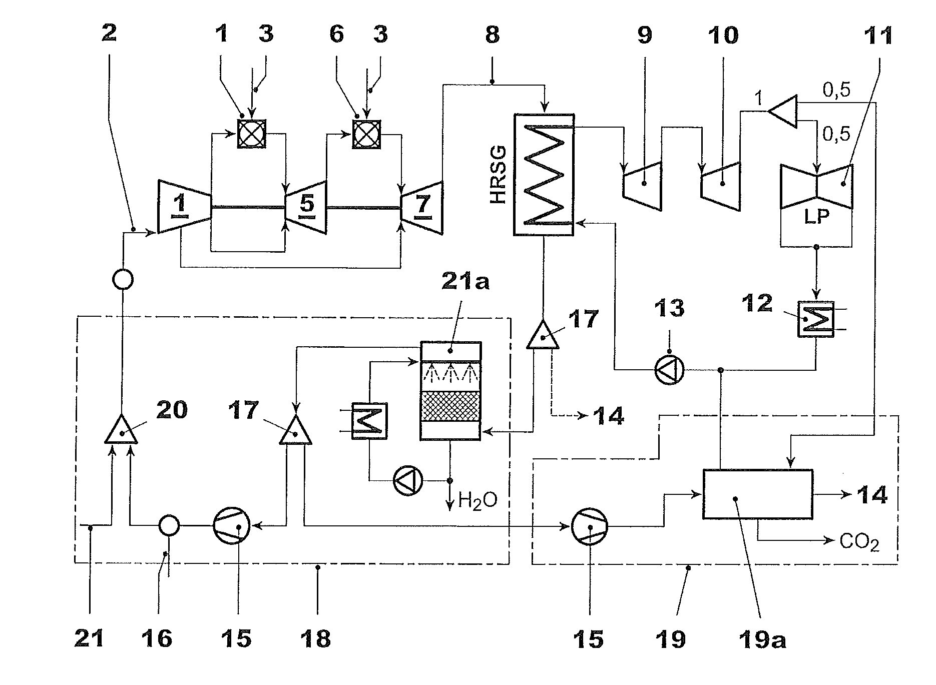
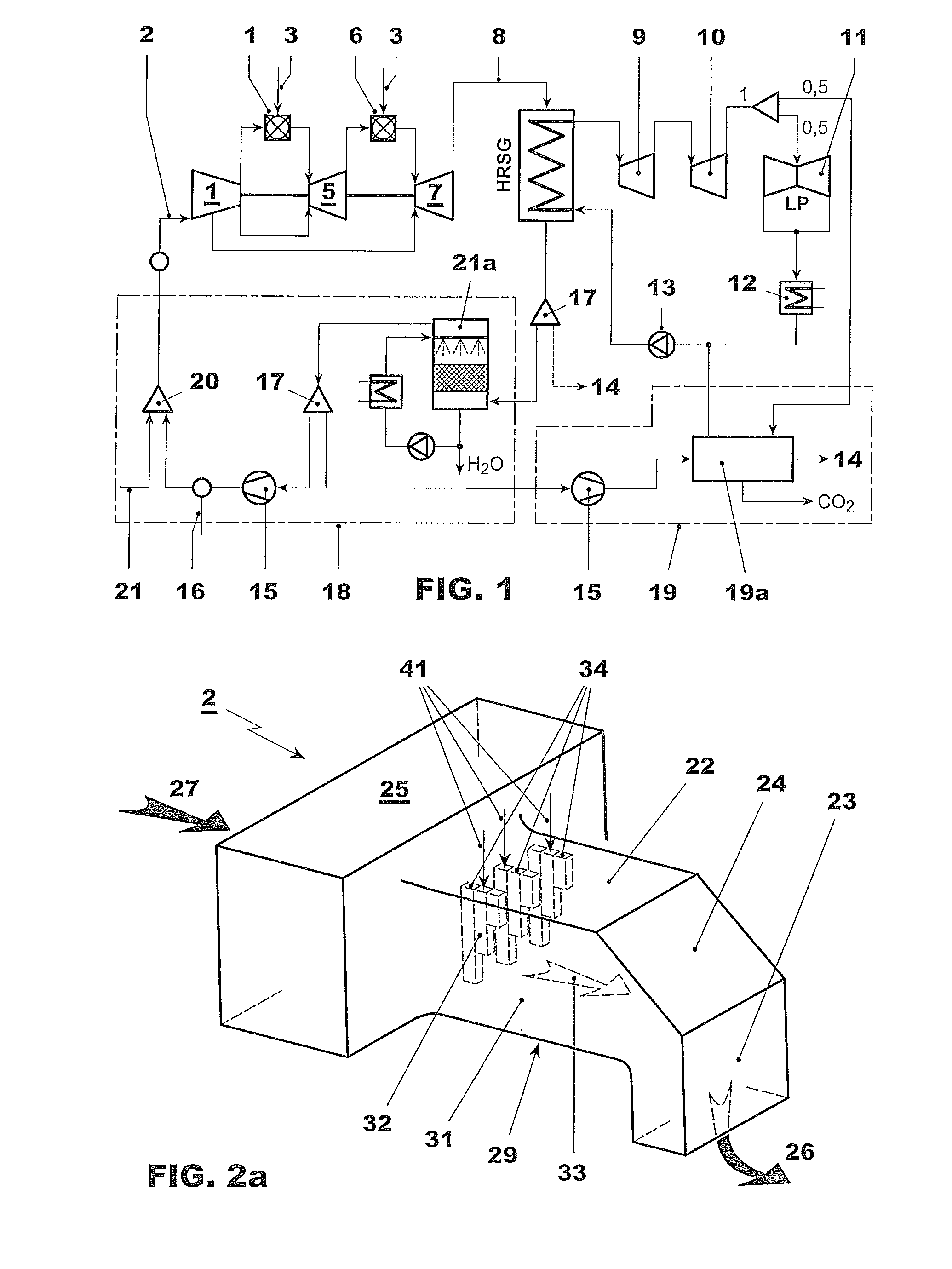
[0031]FIG. 1 shows a general schematic set up of a combined cycle power plant with flue gas recirculation. In a compressor 1 intake air is compressed and introduced to a first combustor 4, supplied with fuel 3, and the resulting combustion air passes a high pressure turbine 5, downstream of which a second combustor 6 is located, downstream of which in a low pressure turbine 7 the exhaust gases are expanded as much as possible. Downstream of the low pressure turbine 7 a heat recovery steam generator 8 is located by means of which, using the heat in the exhaust gases, steam is generated for driving steam turbines. The steam is expanded in a first stage in a high pressure steam turbine 9, followed by an intermediate pressure steam turbine 10 and subsequent to this by a low pressure steam turbine 11, where usually means are provided for by-passing the low pressure steam turbine 11. Downstream of the low pressure steam turbine 11 a condenser 12 condenses the steam to water, which is subs...


PUM

PropertyMeasurementUnit
Flow rateaaaaaaaaaa
Lengthaaaaaaaaaa
Heightaaaaaaaaaa

Abstract

The invention pertains to fluegas recirculation in gas turbines, and specifically to an intake section upstream of the inlet of a compressor of a gas turbine unit with fluegas recirculation. The intake section includes at least one section with a flow path defined by sidewalls in which the fresh airflow of the intake air is flowing along a principal airflow direction, including at least one mixing duct extending into the flow path from at least one sidewall. The mixing duct includes an intake at the at least one sidewall for receiving recirculated fluegas, as well as including at least one outlet opening distanced from said sidewall for blowing recirculated fluegas out of the mixing duct into the airflow.

Description

CROSS-REFERENCE TO RELATED APPLICATIONS[0001]This application claims priority to PCT / EP2012 / 050964 filed Jan. 23, 2012, which claims priority to Swiss Application 00115 / 11 filed Jan. 24, 2011, both of which are hereby incorporated in their entirety.TECHNICAL FIELD[0002]The present invention relates to the field of fluegas recirculation in gas turbines, specifically to elements for mixing fluegas with ambient air upstream of the compressor.BACKGROUND[0003]There is a proposal to enrich the carbon dioxide concentration at the gas turbine exhaust by means of a fluegas recirculation (FGR) system, in combination with post-combustion carbon dioxide capture. In this respect reference is made to WO-2010072710 disclosing such a setup. Fluegas recirculation is beneficial for the carbon dioxide capture process because both the concentration of carbon dioxide is increased and the overall mass flow to the carbon dioxide capture unit is reduced. These two aspects result in smaller carbon dioxide c...

Claims


Application Information

Patent Timeline
IPC IPC(8): F02C7/04B01F23/10
CPCF02C7/04F02C3/34F02C7/057F05D2260/2212F05D2260/61Y02E20/16B01F23/10B01F25/31322B01F25/31331
Inventor BENZ, ERIBERTLINDQVIST, NICLAS LARS OLOFTABIKH, ALI MUSTAPHALUNDIN, LARS FILIP
Owner ANSALDO ENERGIA SWITZERLAND AG
Why Eureka
Try Eureka