Gas adsorbing device and vacuum insulation panel provided with same

a technology of gas adsorption and vacuum insulation, which is applied in the direction of separation process, dispersed particle separation, chemistry apparatus and processes, etc., to achieve stable gas adsorption performance, and easy confirmation

Active Publication Date: 2013-11-21
PANASONIC CORP
View PDF4 Cites 10 Cited by
  • Summary
  • Abstract
  • Description
  • Claims
  • Application Information

AI Technical Summary

Benefits of technology

[0029]According to the present invention, it is possible to appropriately provide the gas adsorbing device having the stable gas adsorption performance. Specifically, according to the gas adsorbing device of the present invention, the sealed state under reduced pressure can be easily confirmed by a simple method of applying excitation. With this, it is possible to perform screening of the gas adsorbing device in which the sealing with the sealing material is incomplete, and the gas adsorption performance is unstable. Thus, only the gas adsorbing device having the stable gas adsorption performance can be housed in the device, such as the vacuum insulation panel, which is required to maintain the vacuum. In addition, according to the gas adsorbing device of the present invention, even in the case of performing the heat treatment in a reduced pressure and high temperature atmosphere, by the existence of the heat transfer member, the temperature irregularity of the gas adsorbing material can be reduced, and the gas adsorbing material in the housing container can be subjected to the heat treatment substantially uniformly. Thus, the gas adsorption performance can be stabilized. Further, according to the gas adsorbing device of the present invention, even in the case of performing the heat treatment in a reduced pressure and high temperature atmosphere, a time required to perform the heat treatment of the gas adsorbing material in the housing container can be shortened by the existence of the heat transfer member.

Problems solved by technology

However, when air invades gradually into the vacuum insulation panel through the laminate film, unfortunately the gas heat conduction component increases to gradually increase a thermal conductivity of the vacuum insulation panel.

Method used


Image

  • Gas adsorbing device and vacuum insulation panel provided with same
  • Gas adsorbing device and vacuum insulation panel provided with same
  • Gas adsorbing device and vacuum insulation panel provided with same

Examples


embodiment 1

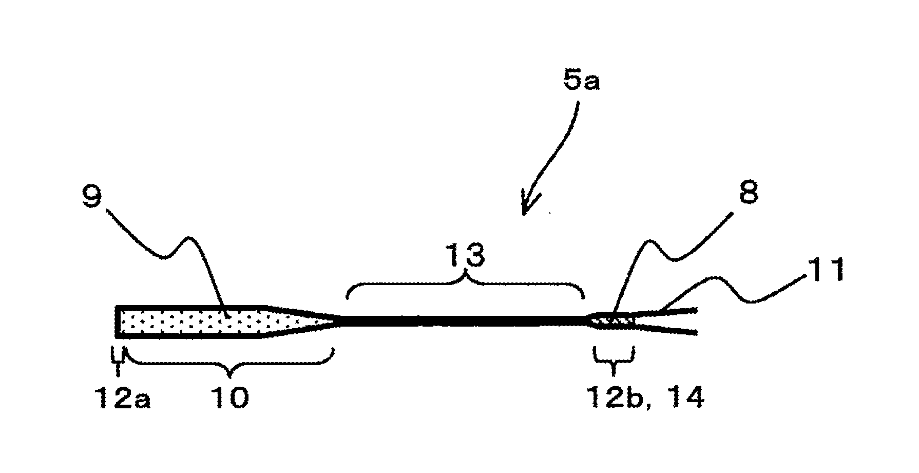
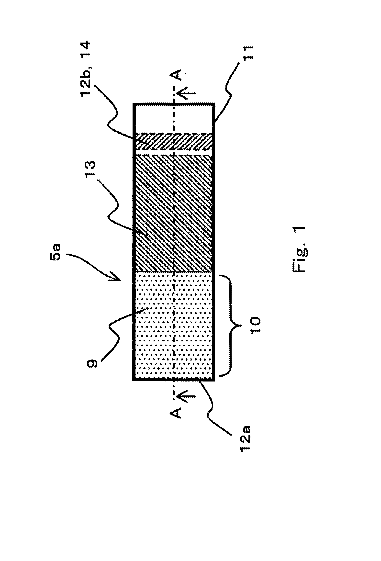
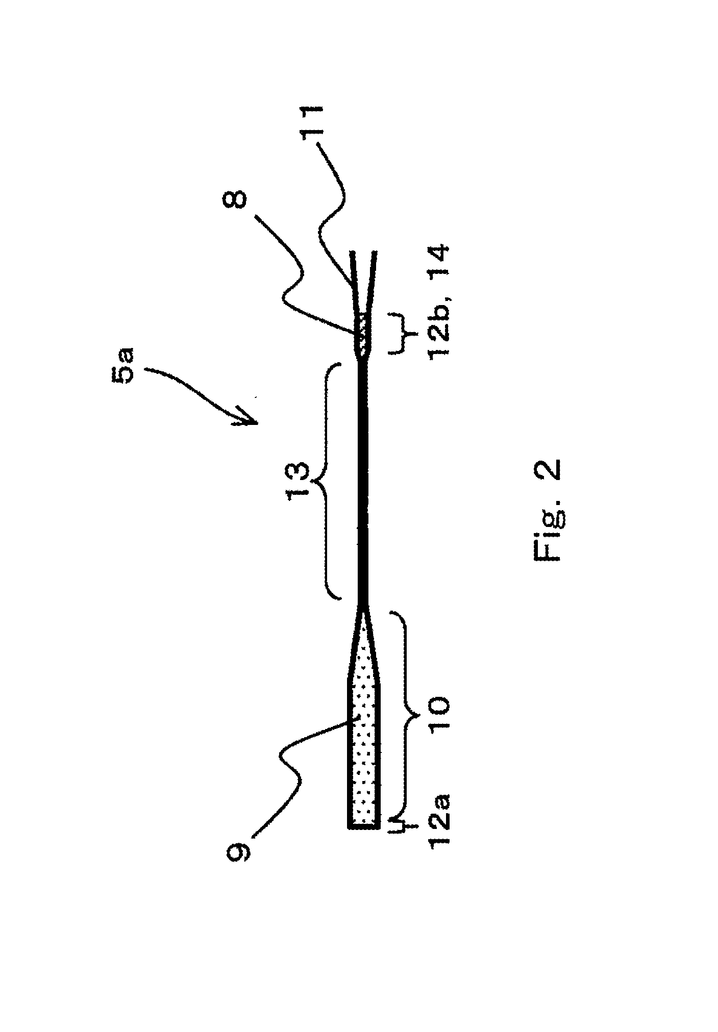
[0076]FIG. 1 is a plan view showing a configuration example of a gas adsorbing device according to Embodiment 1 of the present invention. FIG. 2 is a cross-sectional view taken along line A-A of FIG. 1.

[0077]As shown in FIGS. 1 and 2, a gas adsorbing device 5a according to Embodiment 1 includes: a gas adsorbing material 9 that is made of copper ion-exchanged ZSM-5 zeolite and adsorbs nitrogen; and a housing container 11 that has a long, thin, flat, tubular shape, houses the gas adsorbing material 9 under reduced pressure, and is made of aluminum.

[0078]The housing container 11 includes: a housing portion 10 configured to house the gas adsorbing material 9; and seal portions 12 respectively located at both ends of the housing portion 10. A seal portion 12a that is one of the seal portions 12 respectively located at both ends of the housing portion 10 is a bottom obtained such that the housing container 11 is formed by deep drawing to have a bottomed tubular shape. A seal portion 12b t...

embodiment 2

[0097]FIG. 4 is a plan view showing a configuration example of the gas adsorbing device of Embodiment 2 of the present invention. FIG. 5 is a cross-sectional view taken along line B-B of FIG. 4. FIG. 6 is a cross-sectional view taken along line C-C of FIG. 4.

[0098]As shown in FIGS. 4 to 6, a gas adsorbing device 5b according to the present embodiment includes: the gas adsorbing material 9 that is made of copper ion-exchanged ZSM-5 zeolite and adsorbs nitrogen; and the housing container 11 that has a long, thin, flat, tubular shape and is made of aluminum and in which both sides of the housing portion 10 configured to house the gas adsorbing material 9 under reduced pressure are sealed.

[0099]The seal portion 12a that is one of the seal portions 12 respectively located at both ends of the housing portion 10 is sealed such that the opposing inner surfaces of the housing container 11 are caused to get close to each other to be subjected to the ultrasonic welding. The seal portion 12b is...

embodiment 3

[0109]FIG. 8 is a plan view showing a schematic configuration example of the gas adsorbing device according to Embodiment 3 of the present invention. FIG. 9 is a cross-sectional view taken along line A-A of FIG. 8.

[0110]As shown in FIGS. 8 and 9, a gas adsorbing device 5c according to Embodiment 3 includes: the gas adsorbing material 9 which is made of copper ion-exchanged ZSM-5 zeolite and adsorbs nitrogen and whose air adsorbing performance improves by the heat treatment; the housing container 11 that has a long, thin, substantially flat, tubular shape and is made of aluminum and in which both sides of the housing portion 10 configured to house the gas adsorbing material 9 under reduced pressure are sealed; and one plate-shaped heat transfer member 15 made of a metal material that is higher in the heat-transfer performance than the gas adsorbing material 9 and embedded in the gas adsorbing material 9 in the housing container 11. Although not shown in FIGS. 8 and 9, as with Embodim...


PUM

PropertyMeasurementUnit
diameteraaaaaaaaaa
pressuresaaaaaaaaaa
thicknessaaaaaaaaaa

Abstract

A gas adsorbing device (5a) according to the present invention includes a gas adsorbing material (9) that adsorbs at least nitrogen and a housing container (11) that has a long, thin, flat, tubular shape and is made of metal and in which both sides of a housing portion (10) configured to house the gas adsorbing material (9) under reduced pressure are sealed. A contact portion (13) where opposing inner surfaces of the housing container (11) are in close contact with each other is located between at least one of seal portions (12a and 12b) of the housing container (11) and the housing portion (10).

Description

TECHNICAL FIELD[0001]The present invention relates to a gas adsorbing device and a vacuum insulation panel provided with the same.BACKGROUND ART[0002]Nowadays, an energy-saving promotion becomes increasingly active as a countermeasure against global warming that is one global environmental problem. Particularly, as to heating and cooling devices, a vacuum insulation panel having an excellent heat insulating performance is becoming increasingly common from the viewpoint of efficient use of heat. The vacuum insulation panel is formed such that: a core material, such as glass wool, which has a high gas-phase volume ratio to form fine air gaps, is housed in a gas barrier laminate film formed into a pouched shape; and the laminate film is sealed under reduced pressure. An air gap diameter of the core material is reduced smaller than a mean free path of a gas molecule under reduced pressure, which decreases a gas heat conduction component of the vacuum insulation panel. Particularly, an i...

Claims


Application Information

Patent Timeline
Patent Type & Authority Applications(United States)
IPC IPC(8): B01D53/04
CPCB01D53/0407B01D2251/302B01D2253/108B01D2253/1122B01D2255/20761B01D2257/102B01D2257/104B01D2257/80H01J7/186
Inventor KOJIMA, SHINYAKOSHIYAMA, MASAHIROHASHIDA, MASAMICHIYASUDA, ASAAKI
Owner PANASONIC CORP
Why Eureka
Try Eureka