Hysteretic current mode controller for a bidirectional converter with lossless inductor current sensing

Inactive Publication Date: 2013-11-21
BALANCELL
View PDF7 Cites 27 Cited by
  • Summary
  • Abstract
  • Description
  • Claims
  • Application Information

AI Technical Summary

Benefits of technology

[0006]A method to accomplish stability when closing the loop to control the output voltage of a current mode controlled converter when using a very high gain is described. It uses a simple proportional difference amplifier between the desired output voltag

Problems solved by technology

These methods would be difficult to implement for true bidirectional current mod

Method used


Image

  • Hysteretic current mode controller for a bidirectional converter with lossless inductor current sensing
  • Hysteretic current mode controller for a bidirectional converter with lossless inductor current sensing
  • Hysteretic current mode controller for a bidirectional converter with lossless inductor current sensing

Examples


Embodiment Construction

Current Sense Amplifier

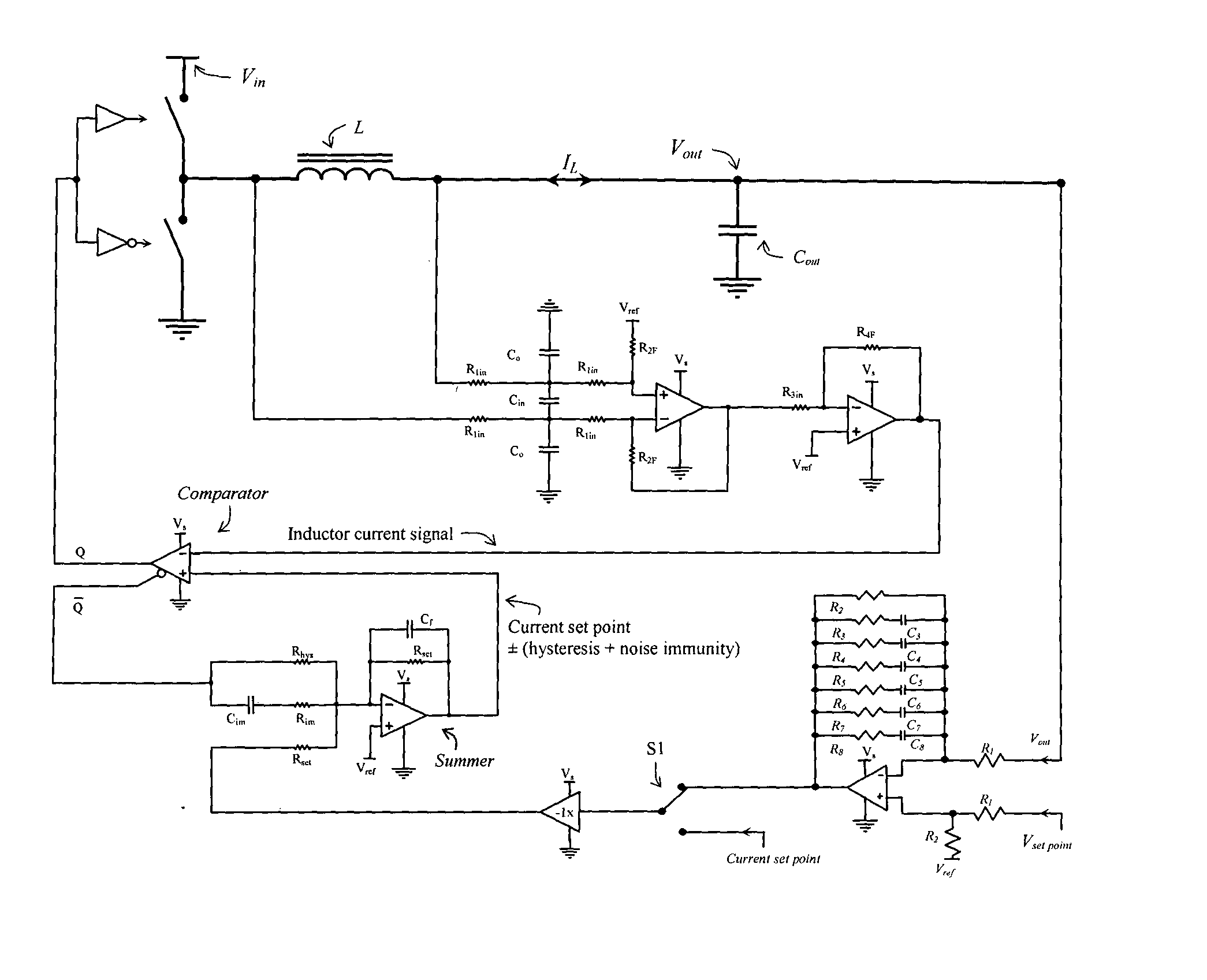
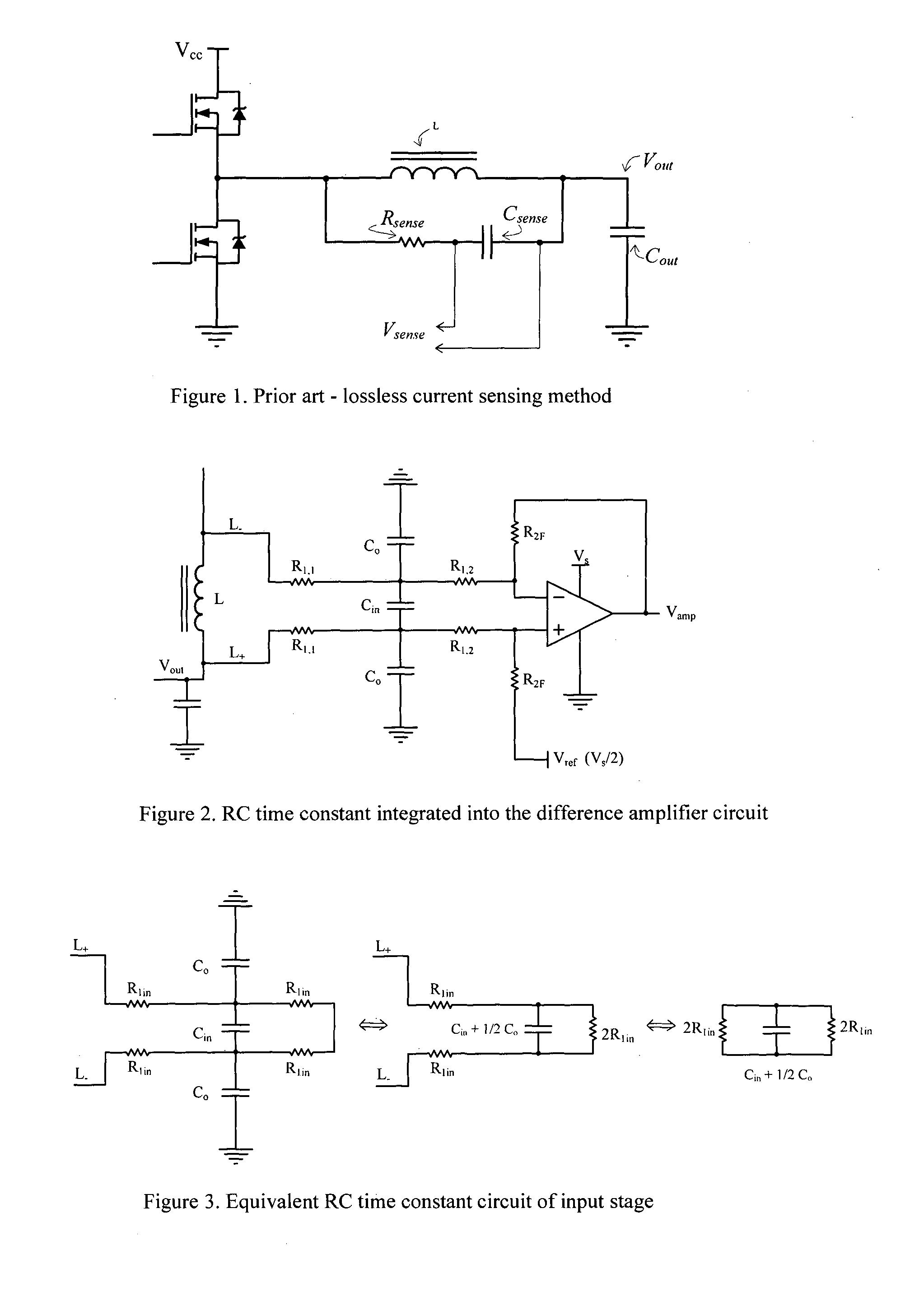
[0019]The first part of this invention is to measure the instantaneous current through the inductor and obtain a voltage representation of it for use in the control circuitry. Firstly, the measurement should be done with as little time delay as possible so as to have as close as possible representation of the instantaneous current through the inductor. Large group delays in the signal mean that the true current could considerably overshoot before control action happens. Delays also add to phase lags and make it more difficult to accomplish overall circuit stability. Secondly, for bidirectional control the current should be measured during all switching cycles. Thirdly the current measurement should add little or negligible additional loss to the converter.

[0020]Adding a current sense resistor in series with the inductor, with suitable amplification, will allow us to attain the first two requisites. However, it adds another lossy component, which for low voltag...


PUM


Abstract

A system and circuit for achieving bidirectional hysteretic current mode control of a converter. The system comprises a summer that provides a constant hysteresis and has added switching noise immunity, a comparator, a lossless inductor current sense means and a converter. A circuit using the inductors internal resistance for sensing the current through an inductor in a lossless manner is described. The circuit preserves both DC and dynamic current information while incorporating the RC time constant, difference amplifier and signal amplification, all using only one amplifier. This circuit provides excellent common mode and differential noise immunity, while still having a high bandwidth and small group delay of the current signal. A method to accomplish stability of a current mode controlled converter when closing the loop to control the output voltage with very high accuracy and gain is described.

Description

BACKGROUND[0001]The advantages of current mode control in a DC-DC converter or DC-AC inverter are well known in the literature. It for most practical purposes reduces a second order system to a first order system making its control and current limiting easier to implement. Peak current or valley mode control are two typical methods of achieving this. These methods either detect only the peak or trough of the inductor current and make assumptions for the other side's limit by having constant off times etc. These methods would be difficult to implement for true bidirectional current mode control as one direction of the current would remain unlimited or uncontrolled. Hence, to attain true bidirectional current mode control, the instantaneous current flowing through the active inductor element should be known at all times (i.e. for both switching cycles) and the inductor ripple current controlled on both sides of the desired set point. This requires that the current through the inductor...

Claims


Application Information

Patent Timeline
IPC IPC(8): H02M3/156G01R27/26H02M1/00
CPCG01R19/0092H02M3/1563H02M3/156G01R27/2611H02M2001/0009H02M1/0009H02M1/0025
Inventor DE VRIES, IAN DOUGLAS
Owner BALANCELL
Why Eureka
Try Eureka