Antenna device and wireless communication device

Active Publication Date: 2013-11-21
MURATA MFG CO LTD
View PDF5 Cites 64 Cited by
  • Summary
  • Abstract
  • Description
  • Claims
  • Application Information

AI Technical Summary

Benefits of technology

[0019]According to an eighth preferred embodiment of the present invention, the sheet conductor preferably includes a resonant circuit that is primarily defined by the slit or the edge of the opening. The resonant frequency of the resonant circuit is preferably the same or substantially the same as the resonant frequency of a circuit that includes the feed coil. With this structure, the radiation efficiency due to the sheet conductor is increased.
[0020]According to a ninth preferred embodiment of the present invention, at least

Problems solved by technology

Thus, a problem arises in that communication may not be able to be performed with another device.
However, the antenna devices described in Japanese Unexamined Patent Application Publication No. 2011-97657 and Japanese Unexamined Patent Application Publication No. 2011-249935 have the following problems.
However, the current that flows in the coil-shaped conductor 31

Method used


Image

  • Antenna device and wireless communication device
  • Antenna device and wireless communication device
  • Antenna device and wireless communication device

Examples


first preferred embodiment

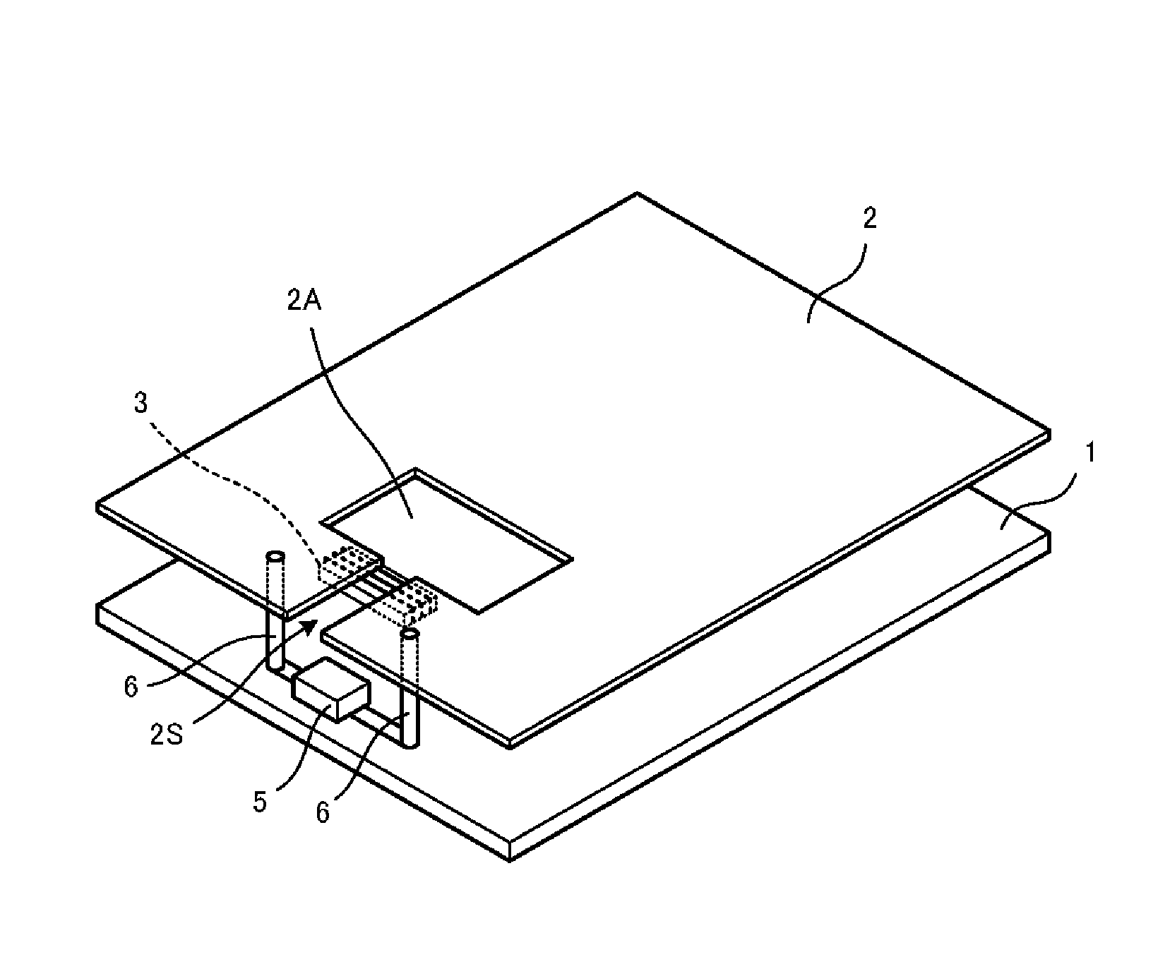
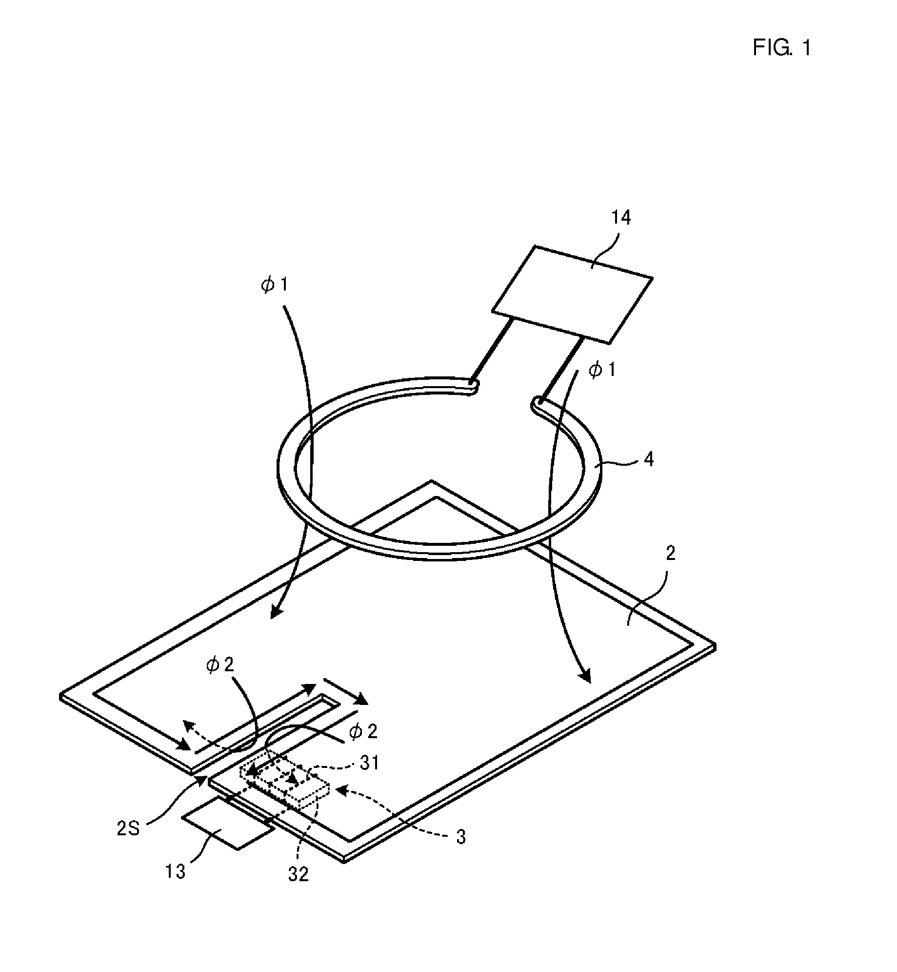
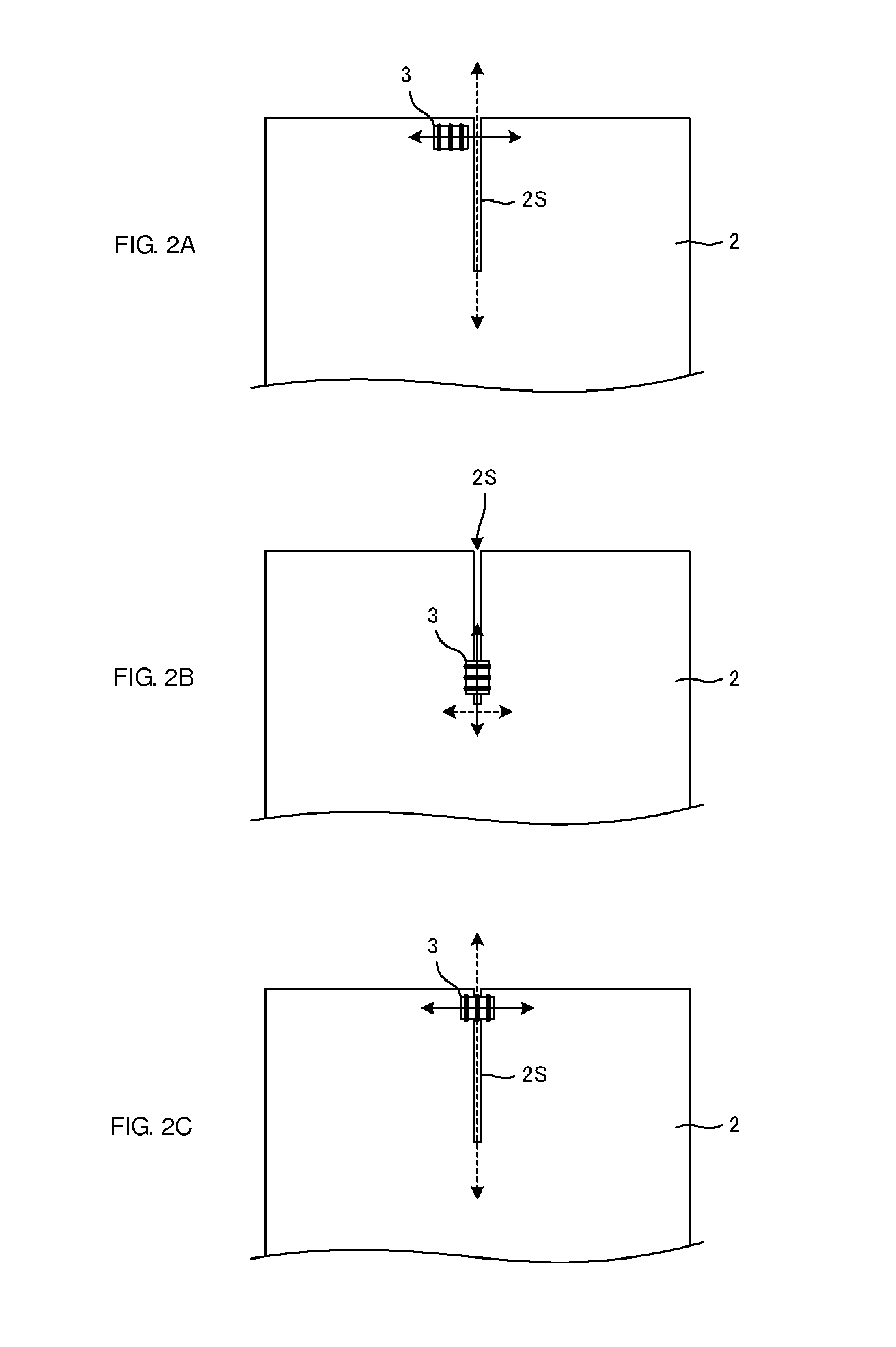
[0054]FIG. 1 is a perspective view of an antenna device according to a first preferred embodiment of the present invention and an antenna coil with which the antenna device performs communication. The antenna device includes a feed coil 3 and a sheet conductor 2. The feed coil 3 includes a magnetic core 32 and a coil-shaped conductor 31, which is arranged around the magnetic core 32. The coil-shaped conductor 31 may preferably be a conducting wire (a wound conductor wire) wound around the magnetic core 32 or may be a conductor pattern provided in a multilayer body including a plurality of stacked dielectric layers, a multilayer body including a plurality of stacked magnetic layers, or a multilayer body including one or more dielectric layers and one or more magnetic layers that are stacked on one another. In particular, the feed coil 3 is preferably a chip-type feed coil that includes, as the coil-shaped conductor 31, a coil-shaped conductor including an in-plane conductor pattern a...

second preferred embodiment

[0068]FIG. 3 is a perspective view of an antenna device according to a second preferred embodiment of the present invention. In this example, a slit provided in the sheet conductor 2 includes slit portions 2Sa and 2Sb, the direction in which the slit portion 2Sa extends being perpendicular or substantially perpendicular to the direction in which the slit portion 2Sb extends. That is, the slit includes a bent portion. A feed coil 3a is preferably arranged such that one of coil openings of the feed coil 3a faces the slit portion 2Sa and the direction of the axis around which the feed coil 3a is disposed is perpendicular or substantially perpendicular to the direction in which the slit portion 2Sa extends. Thus, strong coupling occurs for the feed coil 3a through a magnetic field generated at the slit portion 2Sa. Moreover, a feed coil 3b is preferably arranged such that one of coil openings of the feed coil 3b faces the slit portion 2Sb and the direction of the axis around which the f...

third preferred embodiment

[0074]FIGS. 6A and 6B are perspective views of antenna devices according to a third preferred embodiment of the present invention. Both of FIGS. 6A and 6B illustrate examples in which two sheet conductors 2a and 2b are provided. In addition, the slit 2S is provided between the sheet conductors 2a and 2b. The total area of the sheet conductors 2a and 2b and slit 2S is preferably larger than the area of the feed coil 3. That is, when viewed in a direction perpendicular or substantially perpendicular to each of the sheet conductors 2a and 2b, the outer dimensions of the sheet conductors 2a and 2b are larger than those of the feed coil 3.

[0075]The feed coil 3 is preferably arranged such that the feed coil 3 is close to the side on which the sheet conductor 2a is provided and one of the coil openings of the feed coil 3 faces the slit 2S and the direction of the axis of the feed coil 3 is perpendicular or substantially perpendicular to the direction in which the slit 2S extends. Thus, sim...


PUM


Abstract

An antenna device includes a feed coil and a sheet conductor. The feed coil includes a magnetic core and a coil-shaped conductor, which is provided around the magnetic core. An RFIC is connected to the feed coil. The sheet conductor has a larger area than the feed coil. A slit that extends from a portion of the edge of the sheet conductor toward the inner side of the sheet conductor is provided in the sheet conductor. The feed coil is arranged such that the direction of the axis around which the feed coil is disposed is parallel or substantially parallel to the directions in which the sheet conductor extends. The feed coil is arranged such that the feed coil is close to the slit and one of coil openings at the ends of the feed coil faces the slit.

Description

BACKGROUND OF THE INVENTION[0001]1. Field of the Invention[0002]The present invention relates to an antenna device preferably for use in a radio frequency identification (RFID) system or in a near field wireless communication system and to a wireless communication device that includes such an antenna device.[0003]2. Description of the Related Art[0004]Generally, for RFID in the 13.56 MHz band such as near field communication (NFC) used for mobile terminals, an RFID chip and a matching device are mounted on a circuit board, an antenna is attached to the inner side of a terminal housing made of resin, and the RFID chip and an antenna are connected via a spring pin or the like in a direct current (DC) manner.[0005]Recent wireless communication devices such as mobile phone terminals have become thinner. In order to cope with insufficient strength due to such thinning, it is increasingly the case that strength is improved by using “more metal” when a housing is made. For example, a resin...

Claims


Application Information

Patent Timeline
IPC IPC(8): H01Q1/50H01Q7/00
CPCH01Q1/50H01Q7/00H01Q1/2225H01Q1/243H01Q1/36H01Q1/44H01Q7/08H01Q13/106G06K19/07H01Q1/46H01Q7/06G06K7/10178G06K19/07794H01Q1/2216
Inventor NAKANO, SHINICHIYOSUI, KUNIAKIKATO, NOBORU
Owner MURATA MFG CO LTD
Why Eureka
Try Eureka