Methods, Systems, and Devices Relating to Wireless Power Transfer

a wireless power transfer and wireless technology, applied in the field of wireless power transfer methods, systems and devices, can solve the problems of increasing the power density and electromagnetic field exposure of the patient, significant discomfort and maintenance of the patient, and prior art tet systems that have not eliminated the risk of infection

Inactive Publication Date: 2013-11-21
SUNSHINE HEART PTY LTD
View PDF6 Cites 34 Cited by
  • Summary
  • Abstract
  • Description
  • Claims
  • Application Information

AI Technical Summary

Benefits of technology

[0013]Example 7 relates to the system according to Example 4, wherein the self-expanding structure compr

Problems solved by technology

However, most fully implanted high current devices are presently powered with percutaneous cables, because a safe high-power battery technology still does not exist.
The cables deliver safe power to the implant, but can cause the patient significant discomfort and require maintenance to prevent infection, which occurs in approximately 40% of these implants.
However, these prior art TET systems have not eliminated the risk of infection because the known systems are bulky and require a

Method used


Image

  • Methods, Systems, and Devices Relating to Wireless Power Transfer
  • Methods, Systems, and Devices Relating to Wireless Power Transfer
  • Methods, Systems, and Devices Relating to Wireless Power Transfer

Examples


example

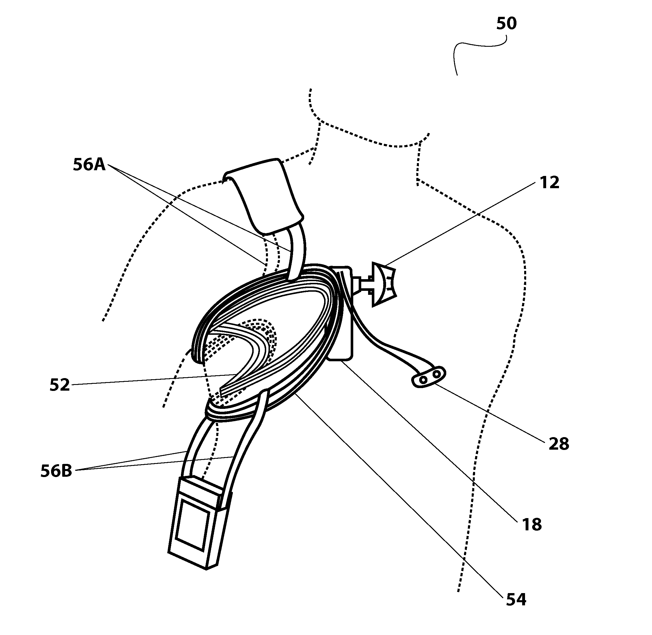
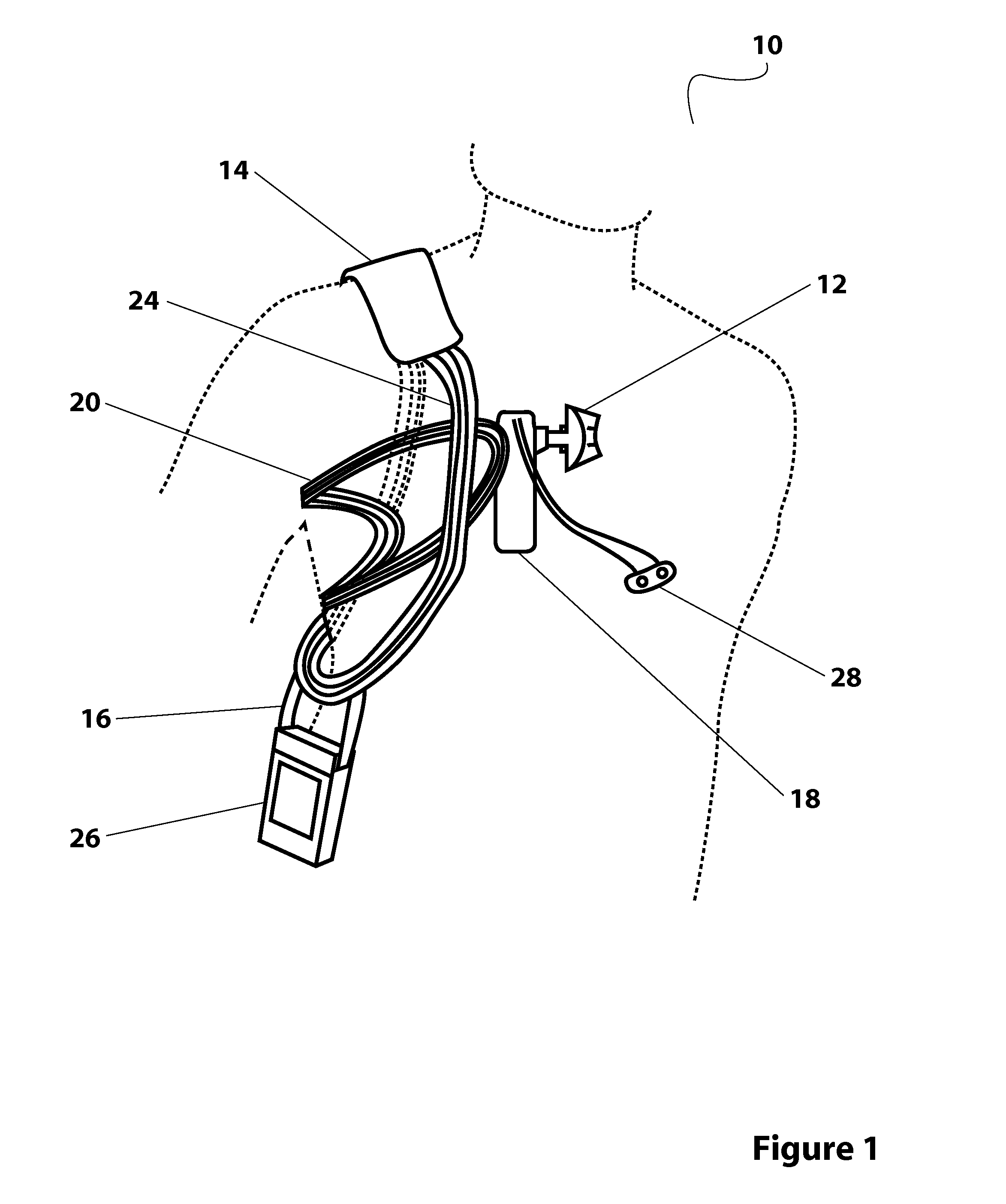
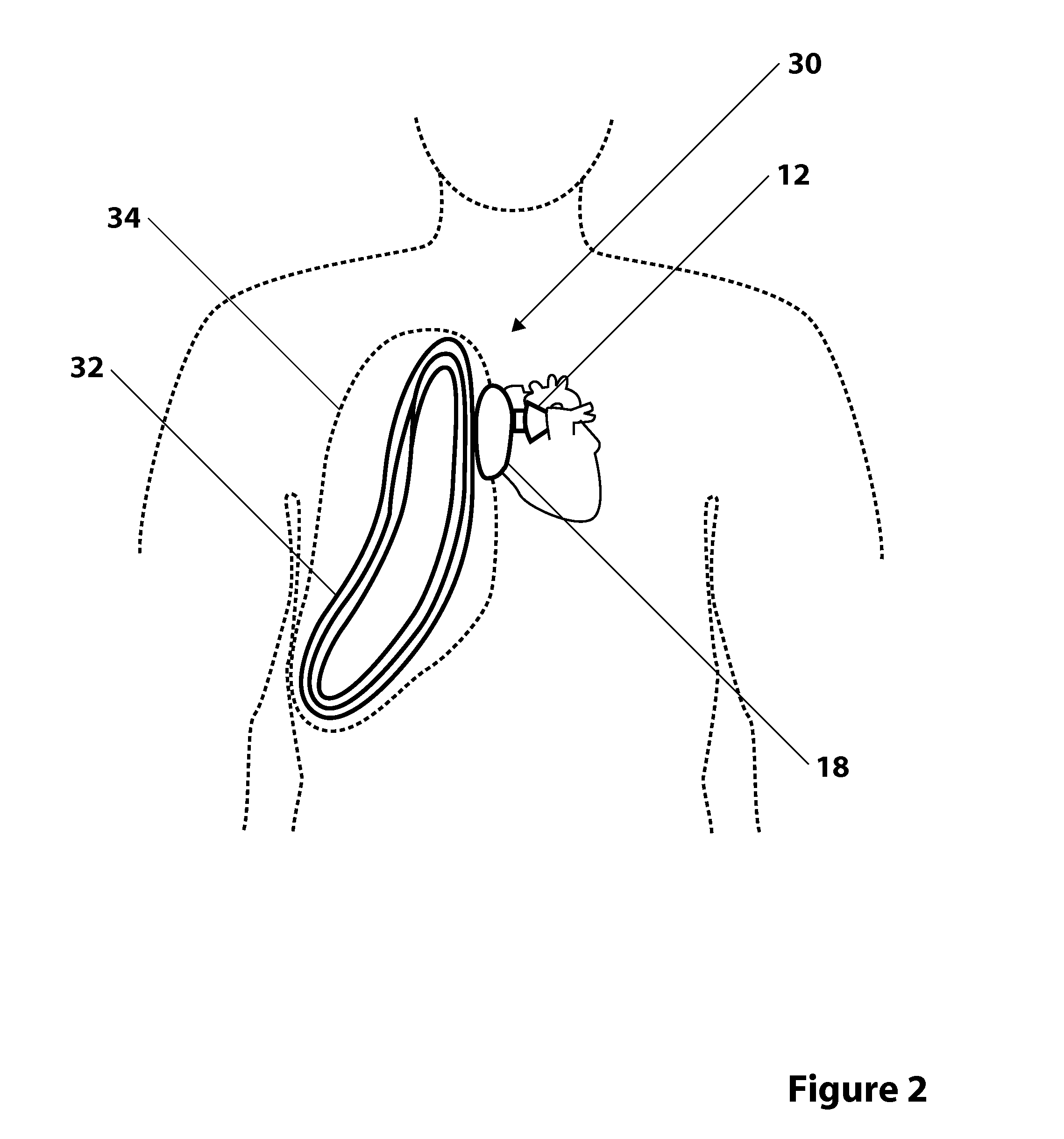
[0069]In one example, the system has an internal coil similar to the coil 20 depicted in FIG. 2. In this example, the coil 20 is 15 cm in width (W) and 25 cm in height (H) as shown in a basic coil 92 description in FIG. 10. The electrical model of the TET system in this example is shown in FIG. 9 and is a classic description of an air core transformer with a signal source and a resonant tuned transmitter coupled by a coupling coefficient M to secondary internal receiver with a resonant tuning and rectifier and control circuitry 90. The operating frequency is largely determined by analysis of tissue absorption and allowed exposure safety limits from regulatory agencies and is discussed further in the exemplary coil design for the test system that follows.

[0070]The effective diameter for this exemplary coil can be determined from the effective coil area. Based on certain simple assumptions, the effective coil diameter of the exemplary coil may be determined by calculating the area of ...


PUM


Abstract

The various embodiments disclosed herein relate to transcutaneous energy transfer systems comprising an internal coil positioned within a cavity of a patient and an external coil inductively coupled to the internal coil. The systems can be coupled to any implantable medical devices, such as, for example, a heart assist device.

Description

CROSS-REFERENCE TO RELATED APPLICATION(S) [0001]This application claims the benefit under 35 U.S.C. §119(e) to U.S. Provisional Patent Application No. 61 / 610,173, filed on Mar. 13, 2012, which is hereby incorporated herein by reference in its entirety.FIELD OF THE INVENTION [0002]The various embodiments disclosed herein relate to methods and devices for transferring electrical power transcutaneously into a cavity of a patient to power electrical therapy devices, including, for example, heart assist devices in the patient's thoracic lung cavity.BACKGROUND OF THE INVENTION[0003]Fully implanted electrical therapy devices have evolved from the battery powered pacemakers to new therapies that require higher levels of energy to be delivered to the body, including nerve stimulation, drug delivery, muscle stimulation (TENS), heart assist technologies, and heart replacement with an artificial heart. The evolution of battery technology has made it possible to implant low power medical devices...

Claims


Application Information

Patent Timeline
IPC IPC(8): A61M1/12
CPCA61M1/127A61N1/3787A61B2560/0219A61M2205/8243H02J7/0042H02J50/50H02J50/12A61M2209/088A61M60/161A61M60/289A61M60/873A61M60/869A61M60/468A61M60/268A61M60/427A61M60/562A61M60/165H02J2310/23A61M60/148
Inventor LAFONTAINE, DANIEL M.
Owner SUNSHINE HEART PTY LTD
Why Eureka
Try Eureka