Plasma Feedwater and/or Make Up Water Energy Transfer System

a technology of energy transfer system and feedwater, which is applied in the direction of combustible gas production, lighting and heating apparatus, combustion types, etc., can solve the problems of poor economics associated with plasma technology, existing plasma projects, and low cost of plasma technology, so as to reduce emissions in the afterburner.

Inactive Publication Date: 2013-12-05
JURANITCH JAMES CHARLES +1
View PDF7 Cites 6 Cited by
  • Summary
  • Abstract
  • Description
  • Claims
  • Application Information

AI Technical Summary

Benefits of technology

[0026]In another embodiment, there is provided the step of injecting recirculated exhaust gas (i.e., EGR) into the afterburner. In other embodiments, the step of injecting recirculated exhaust gas into the afterburner is performed at a flow rate that is varied in response an afterburner temperature characteristic. Exhaust Gas Recirculation (EGR) is used cool the charge and thereby reduce the emissions in the afterburner. This aspect of the invention can be combined with any of less than stoichiometric air injection, e...

Problems solved by technology

If an analysis of plasma waste (or other renewable fuels) relative other energy facilities is conducted, it becomes apparent that the lack of existing plasma projects is not exclusively the result of technological problems, but also results from the relatively poor economics associated with this technology.
Plasma technology is not inexpensive when compared disposition of waste using landfill, incineration, or conventional gasification.
Many plasma projects fail at the onset, notwithstanding extensive initial marketing efforts, usually as a result of inadequate financing and low or nonexistent profitability.
Unfortunately, it is expected that this modest boon to plasma usage will be short lived, as it represents an artificial market that is a po...

Method used


Image

  • Plasma Feedwater and/or Make Up Water Energy Transfer System
  • Plasma Feedwater and/or Make Up Water Energy Transfer System
  • Plasma Feedwater and/or Make Up Water Energy Transfer System

Examples


Embodiment Construction

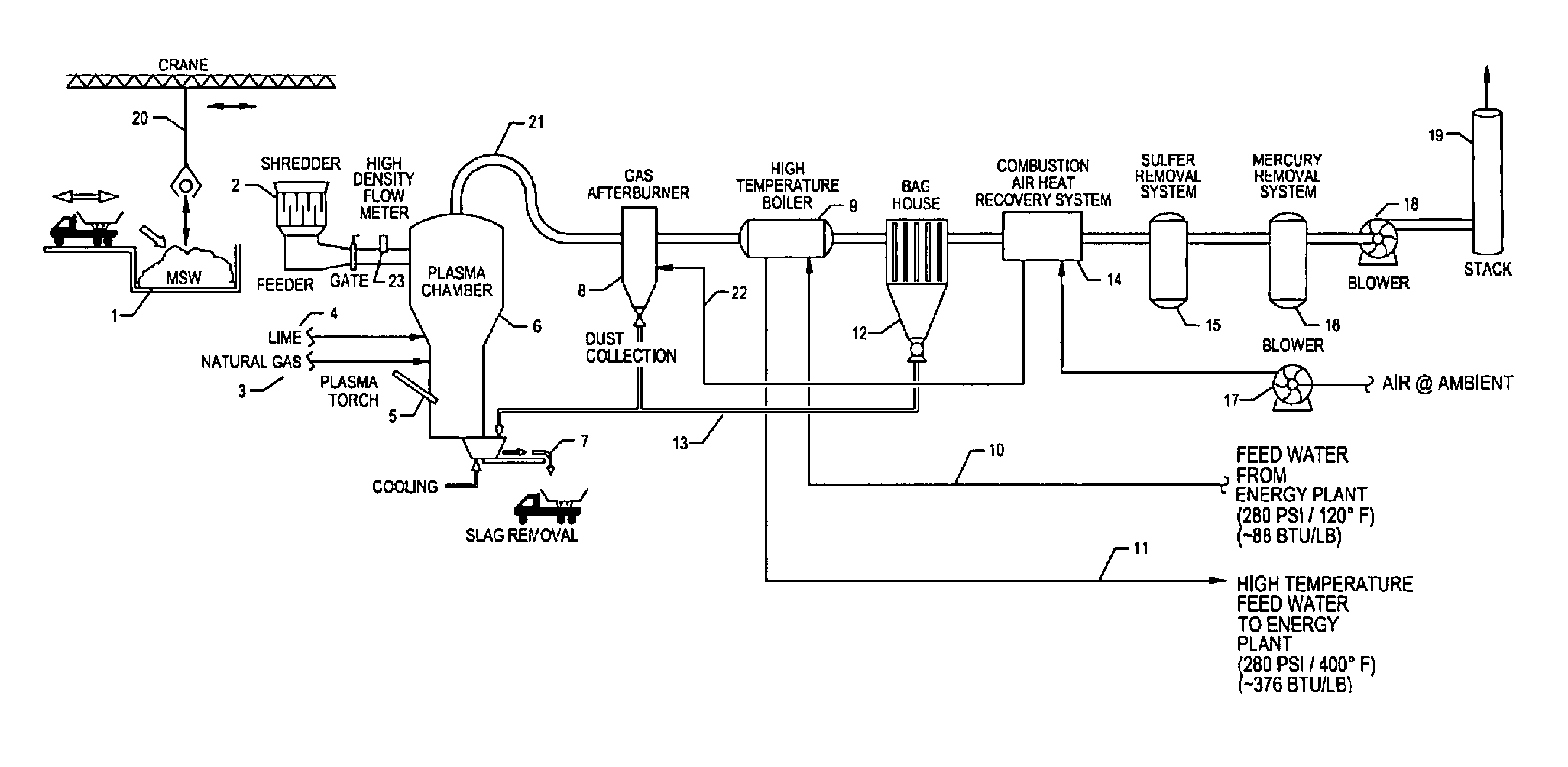
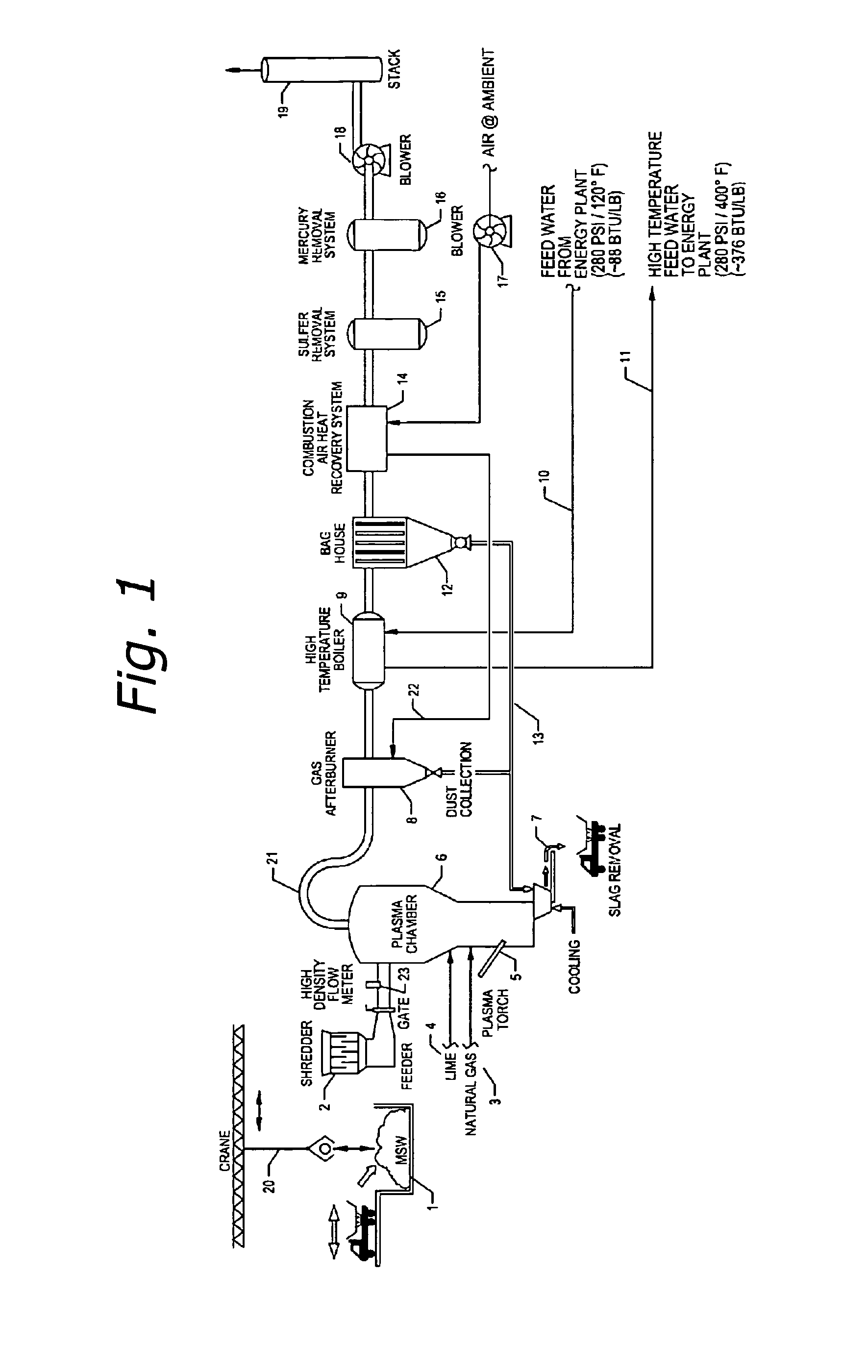
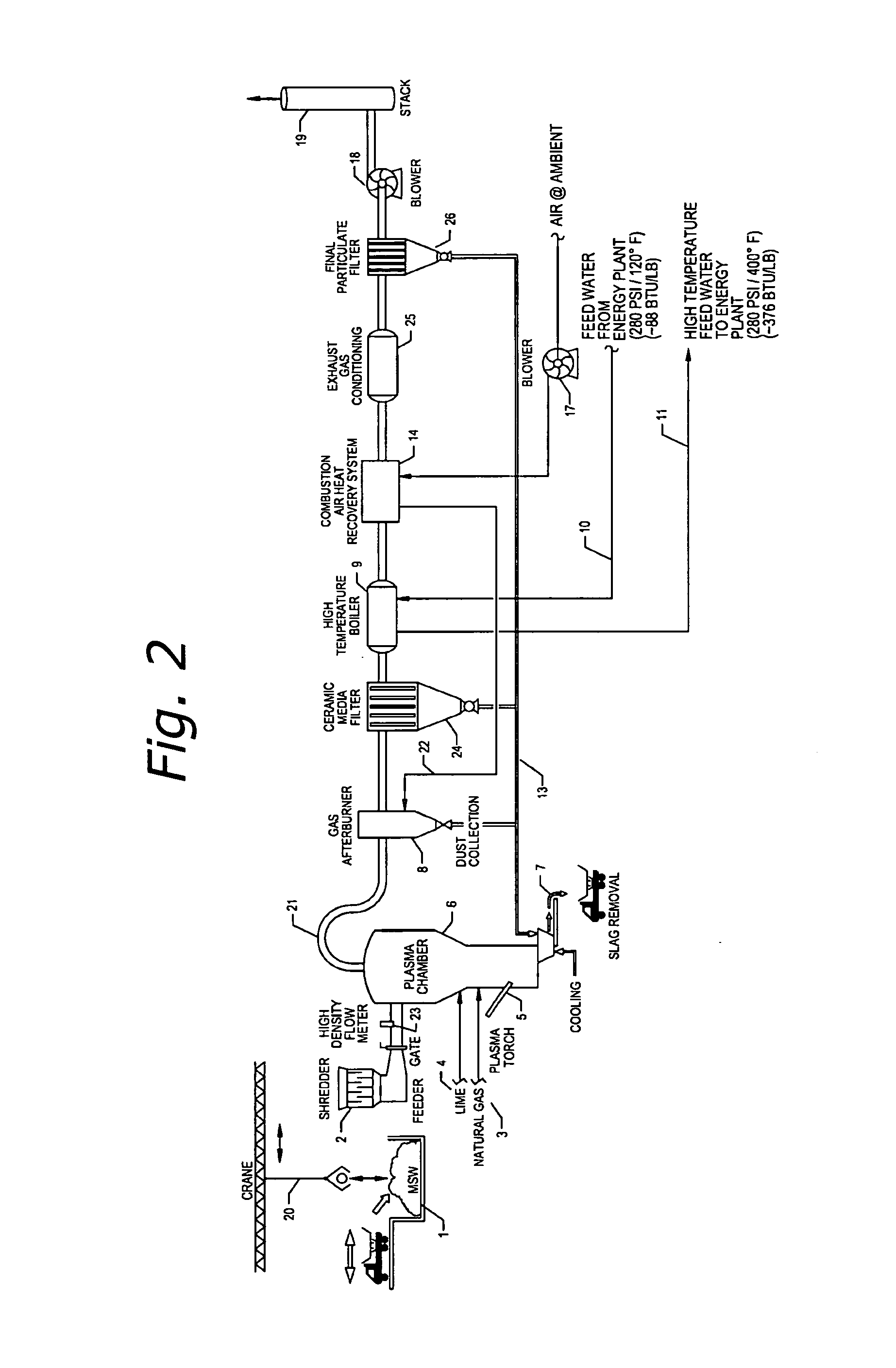
[0044]FIG. 1 is a simplified schematic representation of a process and system for generating energy from a renewable energy source constructed in accordance with the principles of the invention. As shown in this figure, municipal solid waste, designated as MSW 1, or other feedstock, is delivered, in this specific illustrative embodiment of the invention, the system by a crane 20, which unloads same from a truck (not specifically designated). The feedstock can be any organic material, or fossil fuel. Crane 20 transfers MSW 1 a shredder 2. The shredded feedstock (not shown) is then delivered a plasma chamber 6. It is be understood that any other form of gassifier can be employed in the practice of the invention.

[0045]The feed system, which includes shredder 2, compresses the incoming feedstock MSW 1 so as minimize the introduction of air. An in-line, high density flow meter 23 monitors feedstock velocity provide instantaneous feedstock flow rate data. Plasma chamber 6, or other conven...


PUM


Abstract

A method and system for converting a feedstock using thermal plasma or other gassifier, into a feedwater or make up water energy transfer system. Feedstock is any organic material or fossil fuel. The energy transferred in the feedwater or make N up water is used in any Rankine or other steam process, or any process that requires heat. Heat is extracted from a gas product issued by a gassifier and is delivered to a power plant via its feedwater system or make up water system. Preferably, the gassifier is a plasma gassifier and the gas product is syngas that is combusted in an afterburner. A heated air flow and/or EGR flow is provided the afterburner at a variable flow rate that is responsive an operating characteristic of the afterburner.

Description

RELATIONSHIP TO OTHER APPLICATIONS[0001]This application claims the benefit of U.S. Provisional Patent Application Ser. No. 61 / 399,294 filed Jul. 8, 2010; and of U.S. Provisional Patent Application Ser. No. 61 / 403,929, filed Sep. 23, 2010. The disclosures of those provisional patent applications are incorporated herein by reference.BACKGROUND OF THE INVENTION[0002]1. Field of the Invention[0003]This invention relates generally processes and systems for generating electrical power, and more particularly, a process and system that extracts heat energy from the output gas of a gassifier, provides the extracted heat energy the system for generating electrical power via its associated feedwater system or make up water system, and can be applied any heat transfer process, including simple steam generation.[0004]2. Description of the Related Art[0005]There is significant interest in renewable energy projects. Thermal plasma has consistently distinguished itself as a high efficiency, low em...

Claims


Application Information

Patent Timeline
IPC IPC(8): F22D1/00
CPCF22D1/003F23G5/0276F23G5/033F23G5/085F23G5/16F23G5/46F23G5/50F23G2201/303F23G2202/101F23G2206/203F23G2207/30F23G2900/00001C10J3/18C10J2300/0906C10J2300/0946C10J2300/0989C10J2300/0996C10J2300/1238C10J2300/1606C10J2300/165C10J2300/1807Y02E20/12Y02P20/129
Inventor JURANITCH, JAMES CHARLESREYNOLDS, ALAN C.
Owner JURANITCH JAMES CHARLES
Why Eureka
Try Eureka