Electromagnetic device for stabilizing and reducing the deformation of a strip made of ferromagnetic material, and related process

a technology of ferromagnetic material and electromagnet, which is applied in the direction of electrostatic spraying apparatus, electromagnets, cores/yokes, etc., can solve the problems of reducing the effectiveness of action, non-uniform coating distribution, and strong disturbance of the feeding stability of metal strips, so as to reduce the vibration of ferromagnetic strips, eliminate liquid metal leakage, and reduce the deformation of strips

Active Publication Date: 2013-12-05
DANIELI & C OFF MEC SPA
View PDF4 Cites 7 Cited by
  • Summary
  • Abstract
  • Description
  • Claims
  • Application Information

AI Technical Summary

Benefits of technology

[0015]Hence, it is the primary task of the present invention to provide an electromagnetic device for stabilizing and reducing the deformation of a strip made of ferromagnetic material, e.g. a metal strip, during a process for coating the strip. Within the scope of this task, one object of the present invention is to provide an electromagnetic device capable of effectively reducing the vibrations of the ferromagnetic strip and capable of compensating for any static deformation (crossbow) generated in the strip. Another object of the present invention is to provide a device which, within the scope of a process based on the electromagnetic levitation of the liquid metal, is capable of eliminating the liquid metal leakage, induced by the magnetic field required for the levitation of the molten metal. Not last object of the present invention is to provide a device which is reliable and easy to make at competitive costs.

Problems solved by technology

This phenomenon also strongly disturbs the feeding stability of the metal strip 4.
The oscillations and the static deformation of the metal strip 4 indeed induce a non-uniform distribution of the coating and a reduced effectiveness of the action of the gas and / or electromagnetic knives which therefore must operate at greater distances to prevent accidental contact with the metal strip.
In other cases, the feeding speed of the strip is reduced with a subsequent and disadvantageous reduction in productivity.
It is also noted that in the case of the process in FIG. 2, the emission of liquid metal splashes through the inlet opening 9 of pot 111′ also negatively influences the quality of the coating.
Such a phenomenon generates points with different alloy composition on the surface of the metal strip 4 and therefore a poor quality of the metal strip 4.
It is clear from that above that a limited number of electromagnets does not allow all the possible configurations which may be taken on by the metal strip 4, to be corrected.
However, this determines a fast saturation of the electromagnets 13 and possible overload problems.
However, this solution could lead to a substantially “notched” distribution of the forces acting on the metal strip 4 and in a significant increase of the number of power supply and cables required to drive the various electromagnets 13, with subsequent increased complexity of the device also in terms of control and the related costs thereof.
It is apparent that the two last solutions indicated certainly cannot be considered satisfactory because they are only relatively effective in the presence of certain vibration mode shapes, i.e. under certain and well-defined conditions of instability.

Method used


Image

  • Electromagnetic device for stabilizing and reducing the deformation of a strip made of ferromagnetic material, and related process
  • Electromagnetic device for stabilizing and reducing the deformation of a strip made of ferromagnetic material, and related process
  • Electromagnetic device for stabilizing and reducing the deformation of a strip made of ferromagnetic material, and related process

Examples


first embodiment

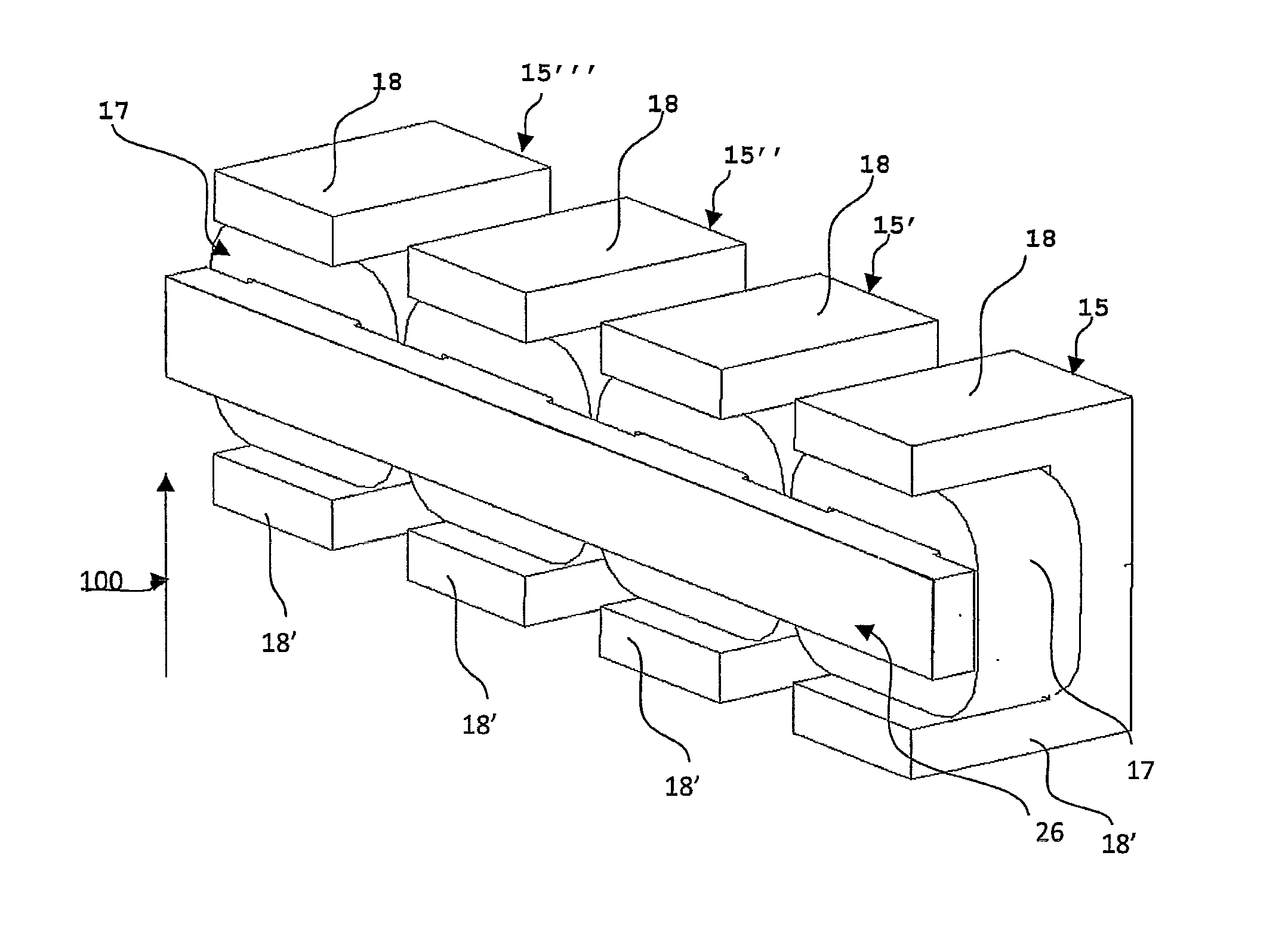
[0042]FIG. 8 is a schematic view relating to device 1 according to the present invention. The first connection element 26 and the second connection element 26′ are preferably made in the shape of a bar with a rectangular section, made of ferromagnetic material, which is laminated or not laminated. As indicated above, the two connection elements 26, 26′ have a mirroring position with respect to the theoretical plane 50 and are arranged so that the longitudinal axis 103 thereof is parallel to the transversal alignment direction 100′ of the electromagnets 15, 15′, 15″, 15″′, 16, 16′, 16″, 16″′, i.e. orthogonal to the transportation direction 100 of strip 4. In particular, according to a preferred embodiment, the two connection elements 26, 26′ have an extension measured along said transversal direction 100′, which is greater than or equal to the extension of strip 4 measured along said transversal direction.

[0043]The first connection element 26 serves the purpose of conveying and distr...

second embodiment

[0055]FIGS. 16 and 17 relate to a device according to the present invention. In this case, device 1 comprises a first connection body 27 which connects the yokes 19 of the first electromagnets 15, 15′, 15″, 15″ to each other. Device 1 also comprises a second connection body 27′ which connects the yokes 19 of the second electromagnets 16, 16′, 16″, 16″′ to each other. In particular, the first connection body 27 connects the rear sections of the yokes 19 of the first electromagnets 15, 15′, 15″, 15′″ to each other. The expression “rear section” in essence means the section of the yoke farthest from the theoretical pass-line 50. As shown in top view in FIG. 16, the second connection body 27′ connects the rear sections of the yokes 19 of the second electromagnets 16, 16′, 16″, 16″′ in an entirely similar way.

[0056]FIGS. 20 and 21 are side views which show the configuration of an electromagnet relating to the electromagnetic device shown in FIGS. 16 and 17. In particular, FIG. 20 shows t...


PUM

PropertyMeasurementUnit
distanceaaaaaaaaaa
distanceaaaaaaaaaa
thicknessaaaaaaaaaa

Abstract

An electromagnetic device (1) for stabilizing and minimizing the deformation of a strip (4) made of ferromagnetic material during its feeding in a system for coating the same strip with molten metal, by applying a distribution of force which is continuous in the direction transversal to the strip regardless of the width thereof. The device comprises first electromagnets and second electromagnets mirroring the first electromagnets with respect to said theoretical pass-line (50) of said strip (4). Each electromagnet includes a core comprising one pole and one feeding coil wound about the pole. The electromagnetic device comprises a connection element (26) made of ferromagnetic material which connects the cores of the first electromagnets (15, 15′, 15″, 15″′) and a connection element (26′) made of ferromagnetic material which connects the cores of the second electromagnets (16, 16′, 16″, 16′). The connection elements (26, 26′) mirror the theoretical pass-line (50) of the strip (4).

Description

FIELD OF THE INVENTION[0001]The present invention falls within the scope of processes and systems for coating flat bodies made of ferromagnetic material such as a steel strip. In particular, the invention relates to a device for stabilizing a metal strip made of ferromagnetic material within the scope of a process for coating the same metal strip with molten metal (e.g. a galvanizing process). The present invention also relates to a system for coating a metal strip with molten metal comprising said electromagnetic device. Lastly, the present invention relates to a process for stabilizing and / or correcting the deformation of a strip made of ferromagnetic material, such as e.g. a metal strip.STATE OF THE ART[0002]As known, strips made of ferromagnetic material, such as e.g. metal strips, are coated on the outside by means of a suitable coating process. With reference to FIG. 1, a first conventional coating process provides passing the metal strip 4 in a molten metal bath 7 contained i...

Claims


Application Information

Patent Timeline
Patent Type & Authority Applications(United States)
IPC IPC(8): B05C13/02B65G43/00H01F7/06
CPCB05C13/02H01F7/06B65G43/00B21B37/007C23C2/40C23C2/00344C23C2/0035C23C2/5245C23C2/524B21B37/00C23C2/24C23C2/003
Inventor GUASTINI, FABIOMINEN, MICHELE
Owner DANIELI & C OFF MEC SPA
Why Eureka
Try Eureka