
Method for manufacturing toilet roll products and toilet roll products

Active Publication Date: 2013-12-05
DAIO PAPER CORP
View PDF33 Cites 18 Cited by
  • Summary
  • Abstract
  • Description
  • Claims
  • Application Information

AI Technical Summary

Benefits of technology

The present invention is a method for manufacturing toilet rolls using a continuous sheet that is applied with chemicals in a ply machine and is wound once to create a secondary paper roll. This secondary roll is then combined with a log in a winder to create the toilet roll. By using a ply machine to apply chemicals to the continuous sheet, the method allows for the use of common equipment in both toilet roll and tissue paper production, which saves space and reduces investment costs. Additionally, the method requires minimal modifications to existing ply machines, further reducing facility investment.

Problems solved by technology

Further, for a patient who suffers from a hemorrhoid disease or the like, it is difficult to rub the skin strongly with the paper in cleaning operation after excretion.
However, the conventional toilet rolls applied with chemicals are expensive with low productivity.
Further, the toilet roll is not sufficiently improved in all the characteristics and does not satisfy the user's demand.
For this reason, the conventional toilet roll products applied with chemicals have not been widely used.
However, in the technique of Patent Literature 1, since the chemicals are applied only by the tips of the embossing convex portions to the continuous sheet, the amount of applied chemicals is small.
Further, there is a concern that the chemicals may not be applied to an embossing concave surface.
For this reason, it is difficult to sufficiently improve the surface lubrication property and the moisture-retaining property.
Further, since chemicals applying process in which the paper strength is the lowest, and the embossing process, in which the continuous sheet are nipped with a predetermined pressure, are performed at the same time, paper breakage may be easily occurred and hence these processes need to be performed at a low speed.
For this reason, it is difficult to improve the productivity.
However, even in the technique of Patent Literature 2, since the log is manufactured immediately after applying the chemicals, the chemicals tend to spread in the sheet after manufacturing the log, and hence there is a disadvantage that the log tends to loose the shape and deviate in winding due to stretching of the sheet caused by stretching of crepe.
Particularly, since the log is cut, at a post stage, into a toilet roll, once the log deviates in winding or looses the shape, which causes defective toilet roll products, this means the yield is degraded, leading to low productivity.
Further, as in Patent Literature 1, since the log is manufactured immediately after the chemicals application applying process, the tension control is difficult, paper breakage may be easily occurred on forming perforation lines on the sheet and the tension of the continuous sheet is decreased, thereby the processing speed needs to be decreased.
Accordingly, the productivity cannot be improved.
Further, in the technique of Patent Literature 2, since the chemicals are applied particularly by spray application after the embossing, the embossing may easily loose shape thereof.
Furthermore, the amount of the ejected chemicals is limited because of the spraying in the winder, so, if the operation would not be performed at a low speed, the amount of applied chemicals to the continuous sheet would be insufficient, which leads inevitably to low productivity.
Since this condition may cause the tearing of the sheet and stop of the manufacturing line for a cleaning operation, the productivity cannot be improved.
In such a toilet roll, the surface lubrication property can be sufficiently improved, but the moisture-retaining property is not sufficient.
Further, for the toilet roll which uses oily chemicals, it is difficult to obtain the water disintegration property necessary for the toilet roll.

Method used


Image

  • Method for manufacturing toilet roll products and toilet roll products
  • Method for manufacturing toilet roll products and toilet roll products
  • Method for manufacturing toilet roll products and toilet roll products

Examples


first embodiment

; Embossing is not Performed

[0141][Paper-Manufacturing Process: Method and Facility for Manufacturing Primary Paper Roll]

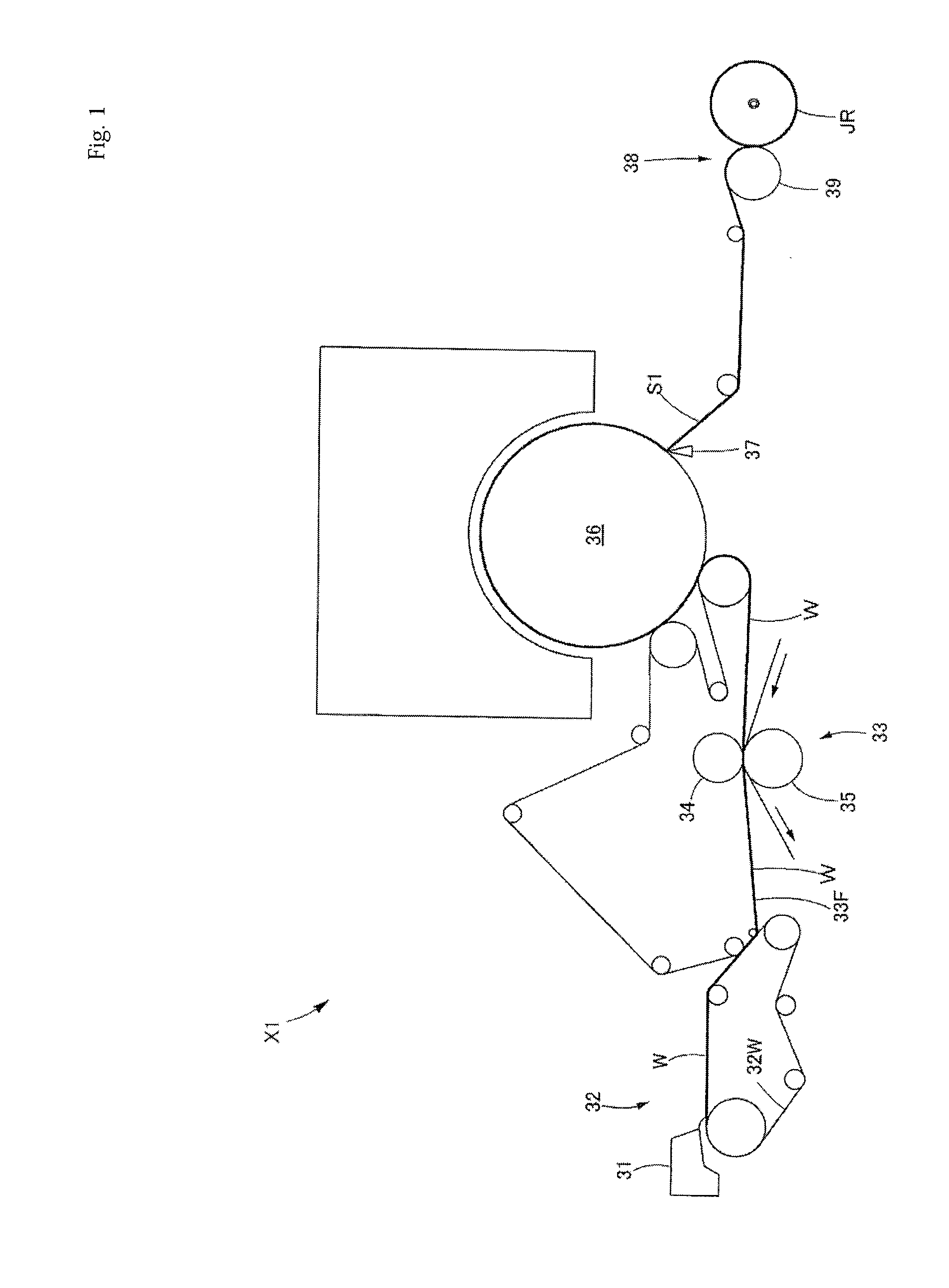
[0142]A primary paper roll JR (referred to as a jumbo roll) according to the present invention may be manufactured as below by an exemplary paper manufacturing machine X1 illustrated in FIG. 1.

[0143]First, a paper material, which has been adjusted in advance by adding appropriate chemicals from a head box 31 to pulp slurry, is supplied onto a wire 32w of a wire part 32 so as to form wet paper W (forming process). Then, the wet paper W is conveyed to a felt 33F of a press part 33 and is dewatered by being nipped between a pair of dewatering rolls 34 and 35 (dewatering process).

[0144]Subsequently, the dewatered wet paper W is attached to a surface of a Yankee dryer 36 so as to be dried. Then, the dried paper was separated therefrom with a doctor blade 37 so as to be dry base paper S1 (single-sheet from the primary paper roll as described later) with crepe (drying pr...

second embodiment

is Performed by Ply Machine

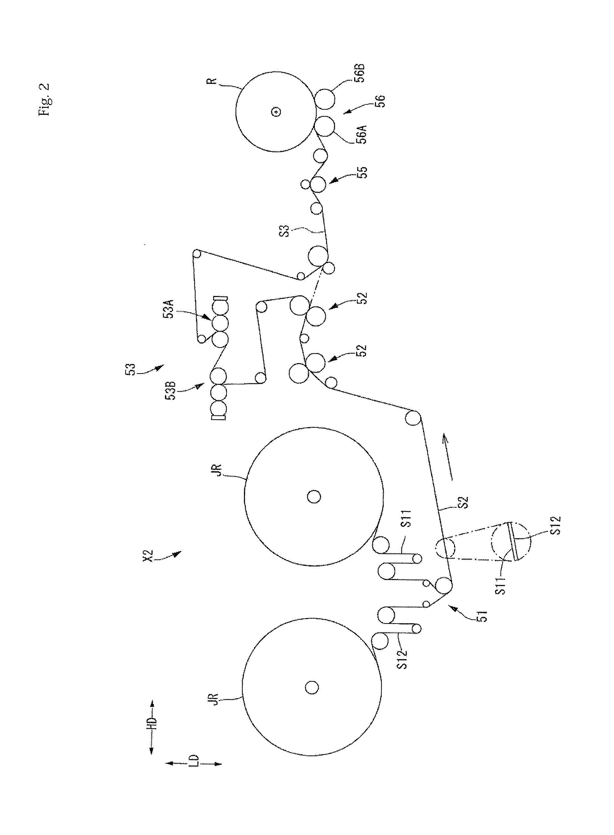
[0227]Subsequently, the second embodiment of the present invention will be described by particularly referring to FIGS. 9 and 10. The second embodiment is the same as the first embodiment except that so-called single embossing is performed on multi-ply continuous sheets S2 and S3 in the ply machine X2, thus, the other matters are as stated before.

[0228]As illustrated in FIG. 9, in the ply machine X2 according to the second embodiment, an embossing unit 60 is provided at the post stage of a chemicals applying unit 53. Then, in the embossing unit 60, embossing is performed on the multi-ply continuous sheet S3 applied with chemicals by the chemicals applying unit 53. Furthermore, the embossing mentioned herein is different from the above mentioned ply-bonding CE, which prevents the ply-separating and is applied to the entire sheet surface so as to improve bulkiness, design property, and surface property of the sheet, referred to as micro embossing, macro embo...

third embodiment

is Performed by Ply Machine

[0237]Subsequently, the third embodiment of the present invention will be described by particularly referring to FIG. 11. The third embodiment is the same as the first embodiment except that so-called double embossing is performed on a multi-ply continuous sheet in the ply machine X2, and by employing this configuration, some requirements related thereto are caused, thus, the other matters are as stated before. Further, as for an embossing unit 60, a structure in which the embossing is performed, conditions for embossing, and the like are the same as those of the second embodiment, and these matters are as stated before.

[0238]Hereinafter, difference from the first embodiment and the second embodiment will be described in detail. The ply-machine X2 according to the third embodiment illustrated in FIG. 11 is sequentially provided with a multi-ply forming unit 51, which performs multi-ply forming on single-sheets S1 and S12 from primary paper rolls so as to f...


PUM

PropertyMeasurementUnit
Diameteraaaaaaaaaa
Speedaaaaaaaaaa
Widthaaaaaaaaaa

Abstract

Provided are an electrolytic cathode structure that can suppress the degradation of an activated cathode even if a reverse current flows upon the stoppage of operation of an electrolyzer in an electrode structure allowing the distance between the electrode and an electrode current collector to be maintained at an approximately constant value, and an electrolyzer using the same.The electrolytic cathode structure includes a metal elastic cushion member 1 compressed and accommodated between an activated cathode 2 and a cathode current collector 3. At least a surface layer of the cathode current collector 3 consumes a larger oxidation current per unit area than the activated cathode. The electrolyzer is partitioned by an ion exchange membrane into an anode chamber for accommodating an anode and a cathode chamber for accommodating a cathode. The electrolytic cathode structure is used for the cathode.

Description

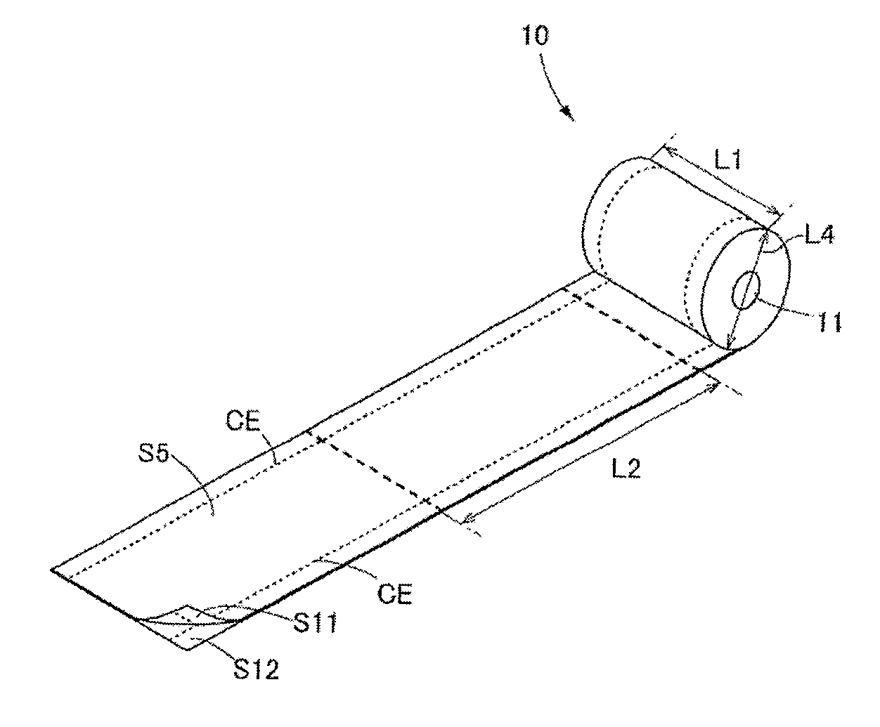
TECHNICAL FIELD[0001]The present invention relates to toilet roll products each manufactured by packing toilet rolls, obtained by winding toilet paper applied with chemicals and having crepe, and a manufacturing method thereof.BACKGROUND ART[0002]Toilet paper is generally made in a form of a toilet roll in which continuous band-like paper is wound on a core called a paper core, and is available in the market as toilet roll products in which a plurality of these toilet rolls are packed.[0003]In the toilet paper, users are interested in a price, a moisture-retaining property (wetness hand feel), flexibility (softness hand feel), and a surface lubrication property (smoothness hand feel), and request high-quality toilet paper in these respects.[0004]Further, for a patient who suffers from a hemorrhoid disease or the like, it is difficult to rub the skin strongly with the paper in cleaning operation after excretion. For this reason, such a patient with a hemorrhoid disease is highly inte...

Claims


Application Information

Patent Timeline
IPC IPC(8): A47K10/16B31F1/07
CPCA47K10/16B31F1/07B31F2201/0761B65H2301/41484B65H2701/1762B31B70/006D21H23/48D21H27/005D21H27/30D21H27/40Y10T428/15A47K10/22D21H1/00
Inventor HIRASAWA, AKIRA
Owner DAIO PAPER CORP
Learn More