
System and Method for Measuring Particles in a Sample Stream of a Flow Cytometer Using Low-Power Laser Source

a flow cytometer and laser source technology, applied in the field of sensor methods and systems, can solve the problems of limiting the acceptance of flow cytometers in broader applications, the cost of typical flow cytometers is more than 30,000 us dollars to purchase, and the use of clinical and laboratory environments. to achieve the effect of low cos

Active Publication Date: 2013-12-12
TRIAD NAT SECURITY LLC
View PDF6 Cites 8 Cited by
  • Summary
  • Abstract
  • Description
  • Claims
  • Application Information

AI Technical Summary

Benefits of technology

The invention provides a way to measure particles in a flow without needing high-power lasers and complex detection system. This is done by using a low-cost and compact laser and detectors, and by transporting the particles at low speed through the focused laser beam. The system can use hydrodynamic or acoustic focusing to increase sensitivity, and a slow flow delivery system can be used to achieve extended transit times. This invention can provide high-sensitivity and resolution detection for flow cytometers and other flow-based analyzers with low-cost components.

Problems solved by technology

Unfortunately, the size and expense of typical flow cytometers currently restricts their use to clinical and laboratory environments.
Such flow cytometers cost more than 30,000 US dollars to purchase.
For many potential users of flow cytometers, instrumentation size and cost are important considerations that may limit the acceptance of these systems in broader applications.

Method used


Image

  • System and Method for Measuring Particles in a Sample Stream of a Flow Cytometer Using Low-Power Laser Source
  • System and Method for Measuring Particles in a Sample Stream of a Flow Cytometer Using Low-Power Laser Source
  • System and Method for Measuring Particles in a Sample Stream of a Flow Cytometer Using Low-Power Laser Source

Examples


experimental examples

and Results

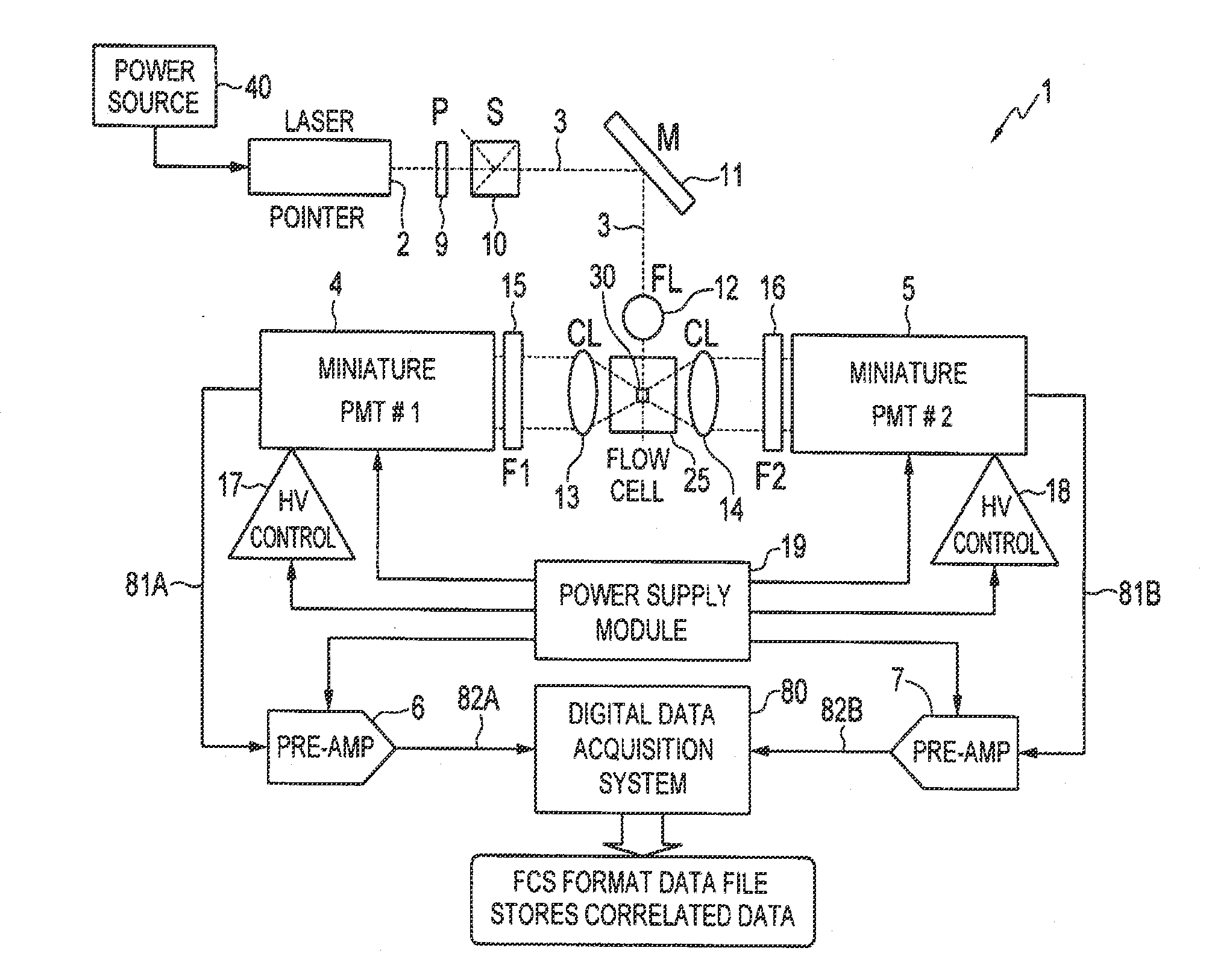
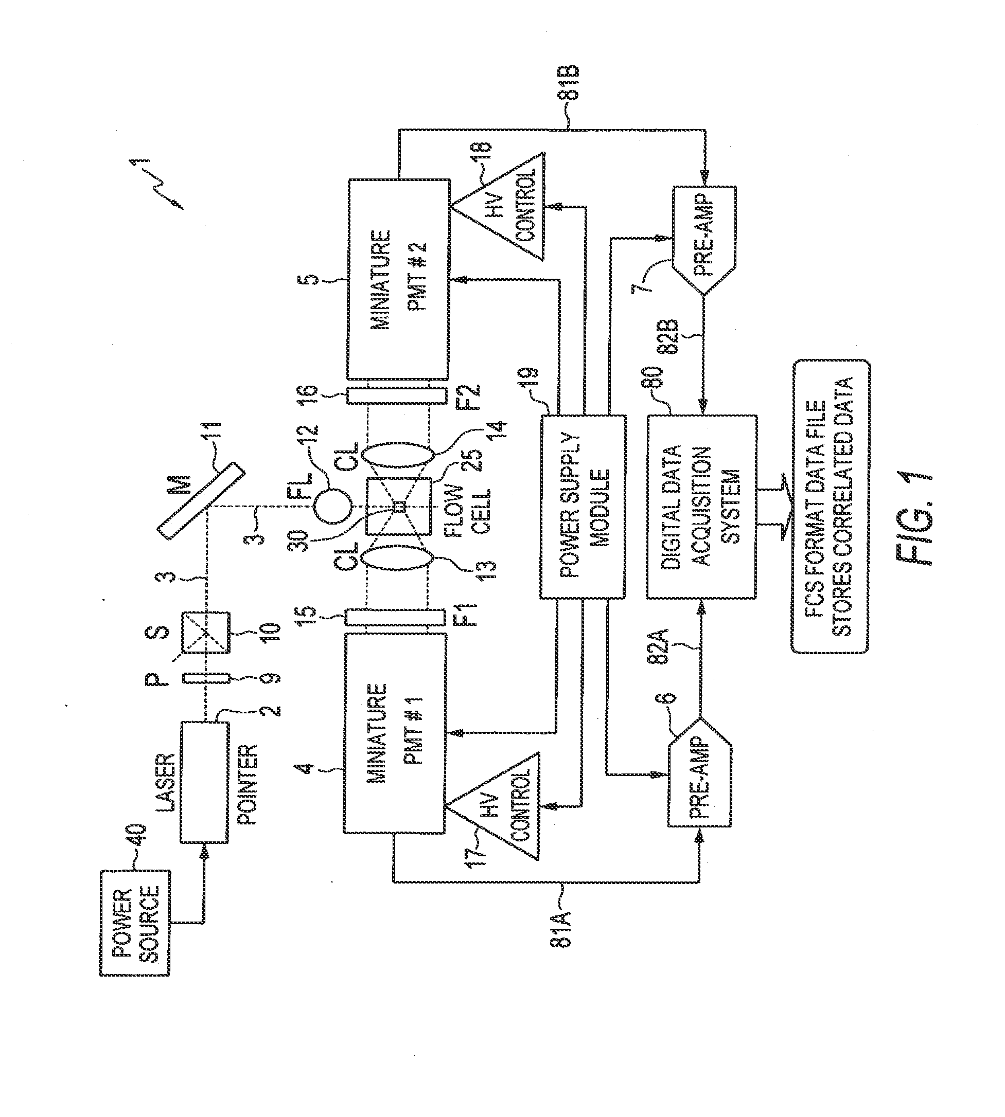
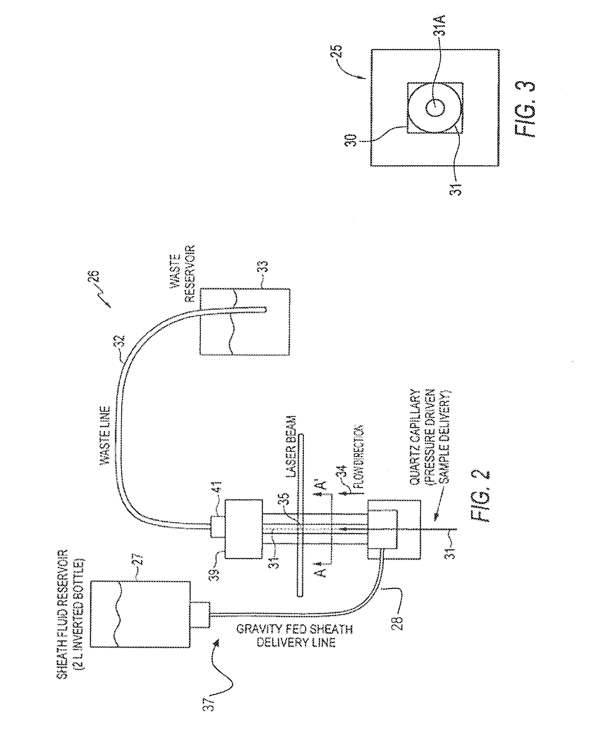
[0054]Specific results that have been obtained using the system and method of interrogating a particle in a sample stream of a flow cytometer according to the illustrative embodiments will now be described in which the interrogated samples were fluorescent calibration microsphere sets. The microsphere samples were concentrated 5-10× via centrifugation prior to use to compensate for the volumetric flow rate in this example (˜0.3-0.6 μl / minute) due to the narrow bore (40 μm ID) quartz capillary tubing utilized to deliver the sample to the flow cell. All microsphere samples were purchased from Spherotech Inc. (Libertyville, Ill.), and included: Rainbow Calibration Particles RCP-30-5A (8 peaks), RCP-20-5 (4 peaks), CP-15-10 (blank 1.87 μm dia.), and CP-25-10 (blank 2.8 μm dia.). The specific type used is given in the text for each example.

[0055]In these examples, the laser 2 was the aforementioned green laser pointer module (532 nm, 3.0 mW, model GMP-532-5F3-CP) from LaserMat...


PUM


Abstract

A system and method for analyzing a particle in a sample stream of a flow cytometer or the like. The system has a light source, such as a laser pointer module, for generating a low powered light beam and a fluidics apparatus which is configured to transport particles in the sample stream at substantially low velocity through the light beam for interrogation. Detectors, such as photomultiplier tubes, are configured to detect optical signals generated in response to the light beam impinging the particles. Signal conditioning circuitry is connected to each of the detectors to condition each detector output into electronic signals for processing and is designed to have a limited frequency response to filter high frequency noise from the detector output signals.

Description

CROSS-REFERENCE TO RELATED APPLICATIONS[0001]This application is a continuation of and now-allowed U.S. patent application Ser. No. 12 / 903,003, filed Oct. 12, 2010. U.S. patent application Ser. No. 12 / 903,003 is a continuation of U.S. patent application Ser. No. 11 / 593,312, filed on Nov. 3, 2006, and later issued as U.S. Pat. No. 7,835,000. The foregoing applications and patents are incorporated by reference herein in their entireties for any and all purposes.STATEMENT OF GOVERNMENT RIGHTS[0002]This invention was made with government support under Contract No. DE-AC52-06NA25396 awarded by the U.S. Department of Energy. The government has certain rights in the invention.TECHNICAL FIELD[0003]Embodiments are generally related to sensor methods and systems. Embodiments are also related to flow sensor analyzers, such as flow cytometers that move particles in a flowing fluid through a sensing region where multiple independent optical measurements are made on the particle. Embodiments are ...

Claims


Application Information

Patent Timeline
Patent Type & Authority Applications(United States)
IPC IPC(8): G01N15/14
CPCG01N15/1434G01N15/147G01N15/1429G01N21/53G01N2015/1413G01N2015/1493
Inventor GRAVES, STEVEN W.HABBERSETT, ROBERT C.
Owner TRIAD NAT SECURITY LLC
Learn More