
Highly Accurate Continuous-Flow Vaporized Fuel Supply for Large Dynamic Power Ranges

a fuel supply and dynamic power range technology, applied in the direction of electrical control, machines/engines, mechanical equipment, etc., can solve the problems of inability to consistently deliver instantaneously on demand fuel across the entire range of operation, general unreliable claimed accuracy, and hugely inaccurate same quarter-gram/second error for near-idle flow rate, etc., to achieve the effect of extreme accuracy

Active Publication Date: 2013-12-19
ECONTROLS LLC
View PDF6 Cites 24 Cited by
  • Summary
  • Abstract
  • Description
  • Claims
  • Application Information

AI Technical Summary

Benefits of technology

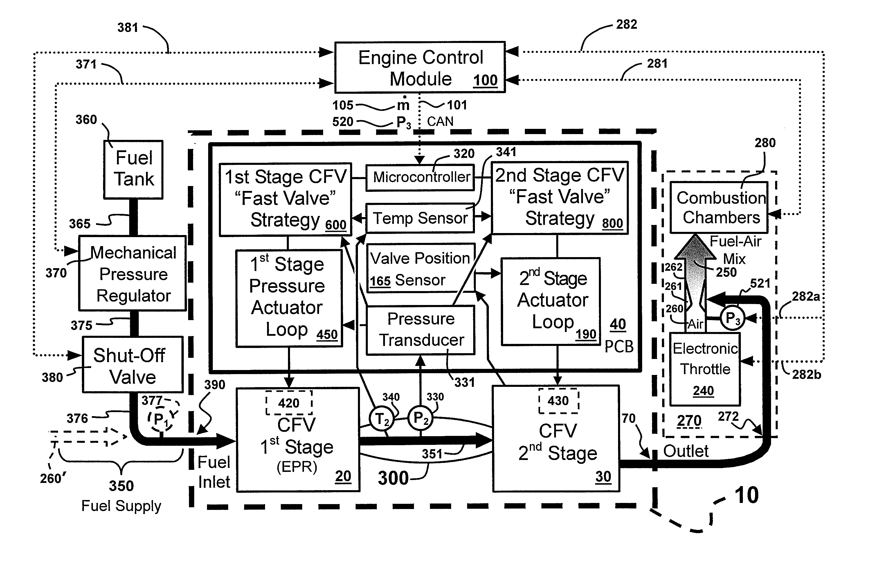
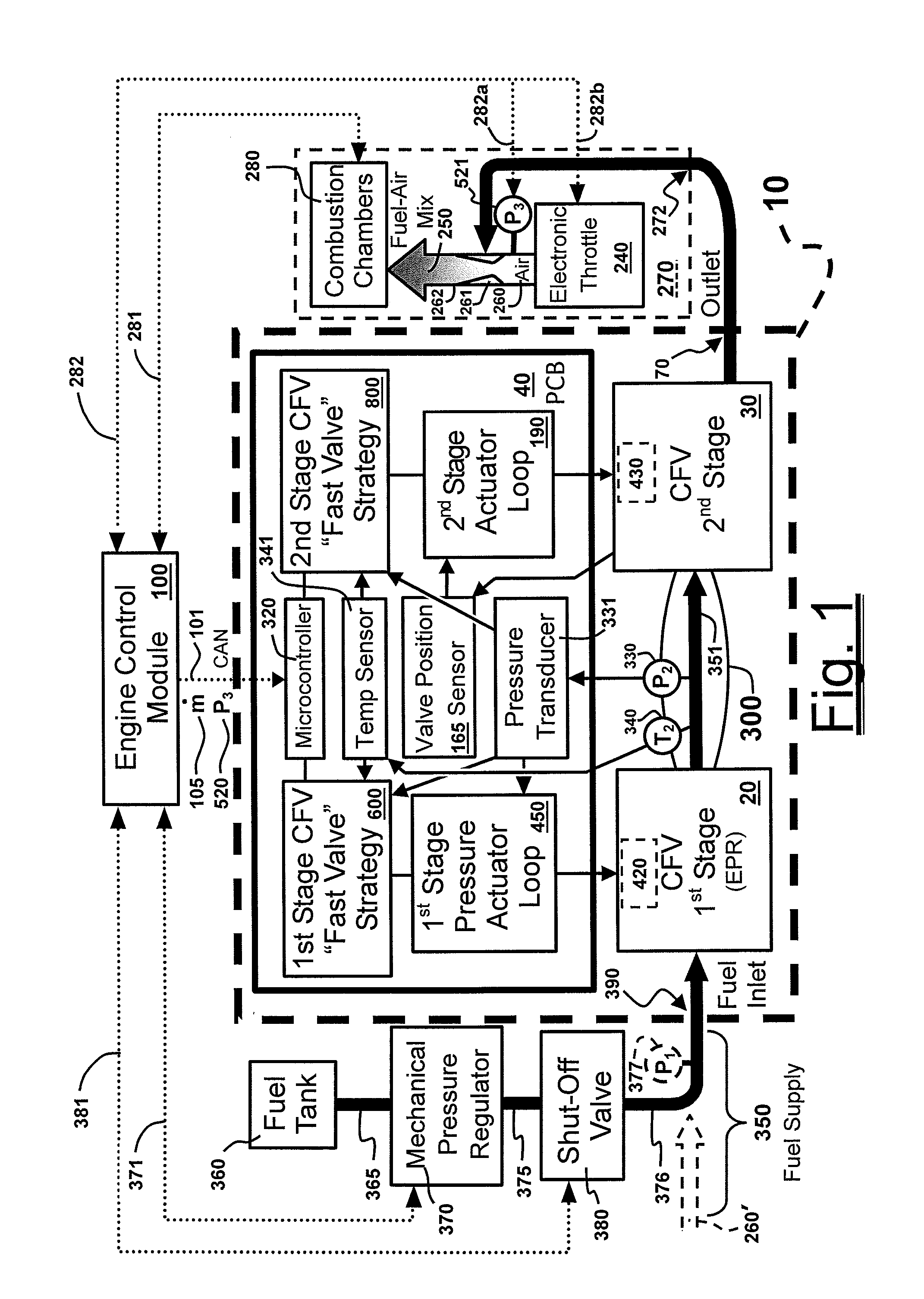
The present invention provides a gaseous fuel flowrate control system for spark-ignited internal combustion engines that is fast-acting and highly accurate. The system can respond to demand signals from the engine's electronic control module and maintain extreme accuracy over large dynamic power ranges, despite pressure fluctuations. This results in multiple benefits, such as improved efficiency, emission controls, and ease of use and repair. The system uses a dual-stage control valve that is adaptable to a variety of applications and capable of achieving extreme accuracy in fuel flowrates. This valve design is radically different from conventional methods and provides many advantages and innovations.

Problems solved by technology

Even though modern ECMs can know the ideal at any given instant, practical fuel supplies are not able to consistently deliver it instantaneously on demand across their entire range of operation.
With the prior art, extreme setpoint accuracies tend to only be attained within a limited range of operation, which means that claimed accuracies are generally unreliable, especially for engine's having large dynamic power ranges.
While calibrating one of the best available valves to a quarter-gram / second error can be manageable for moderate flowrates, the same fuel supply often needs to also idle at about a quarter-gram / second at the opposite end of its operating range, such that the same quarter-gram / second error would be tremendously inaccurate for near-idle flowrates.
So, while prior art gas flow valves claim to deliver extremely accurate flowrates at specified portions of their overall operating range (often at 200 kPa), it has long been unattainable to achieve as much for both ends of the operating range and everything in between, especially for such large ranges in real-world operation.
The complex interaction of too many real-world variables frustrates the pursuit of consistently-high, full-range setpoint accuracies for continuous-flow fuel supplies.
Wear and tear, leaks, lag times, glitches, clogs, noise, artifacts, and general variability all tend to happen in the real world.
Because gaseous fuels are compressible, downstream events related to combustion or valve and piston movements can cause pressure waves that create sizable flowrate fluctuations.
Upstream pressure fluctuations can be equally problematic, especially when controlling the flowrate of vaporized liquid fuels (e.g., LNG or LPG).
The control difficulties with vaporized liquids arise largely due to the dramatic variation in tank pressures during the course of operation.
However, control challenges increase when the tank is full because of the lack of instantaneous vapor pressure capacity, and also when the tank is closer to empty, as the amount of liquid fuel is vaporized over time.
Controlling vaporized liquid fuels is all the more challenging if vaporization is less than complete at the source.
If any residual liquid phase remains after passing through the vaporizer, such as too often occurs when heat exchangers become clogged, dramatic pressure spikes can arise within the flowrate control valve or at other locations that can frustrate the most reliable of control systems.
As a result, conventional gas flow valves do not consistently achieve flowrate setpoint accuracies that are fine enough to ensure optimal power and emissions over large dynamic power ranges.
Even the best of controls are generally unable to consistently achieve and continuously maintain 1% flowrate setpoint accuracies across anything more than about a 15:1 or maybe 20:1 dynamic power range.
Although they produce their specified accuracy in certain easy portions of their operating range, such accuracies are usually limited to the middle or upper half of that operating range, providing overall fuel use and emission levels that fall far short of the idealized levels otherwise expected.

Method used


Image

  • Highly Accurate Continuous-Flow Vaporized Fuel Supply for Large Dynamic Power Ranges
  • Highly Accurate Continuous-Flow Vaporized Fuel Supply for Large Dynamic Power Ranges
  • Highly Accurate Continuous-Flow Vaporized Fuel Supply for Large Dynamic Power Ranges

Examples


Embodiment Construction

[0036]The following examples are described to illustrate preferred embodiments for carrying out the invention in practice, as well as certain preferred alternative embodiments to the extent they seem particularly illuminating at the time of this writing. In the course of understanding these various descriptions of preferred and alternative embodiments, those of skill in the art will be able to gain a greater understanding of not only the invention but also some of the various ways to make and use the invention and embodiments thereof.

Wording Conventions

[0037]For purposes of these descriptions, a few wording simplifications should be understood as universal, except to the extent otherwise clarified in a particular context either in the specification or in any claims. For purposes of understanding descriptions that may be basic to the invention, the use of the term “or” should be presumed to mean “and / or” unless explicitly indicated to refer to alternatives only, or unless the alterna...


PUM


Abstract

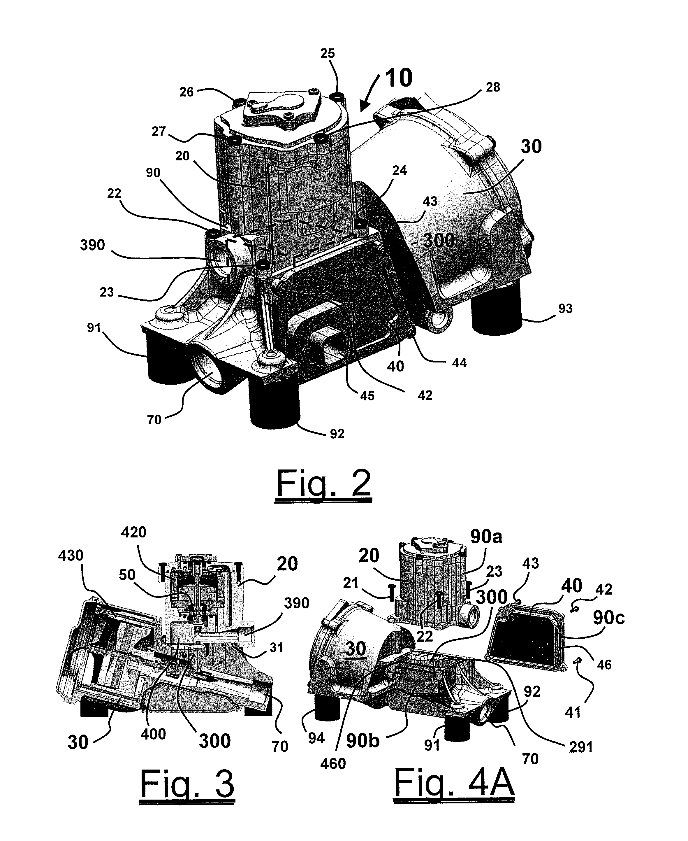
Methods and systems for accurate and precise fuel supply control for continuous-flow of gaseous fuel to an internal combustion engine over a large dynamic power range, including a dual-stage valve that allows optimal control—a first stage in the form of a voice-coil driven electronic pressure regulator, and a second stage in the form of a voice-coil-driven choked-flow valve; monitoring the pressure of the fuel intermediate the two stages and making appropriate adjustments to the first stage via a pressure actuator loop; feeding the gaseous fuel mixture through a unitary block assembly into the second stage; monitoring the pressure of the air / fuel mixture and making appropriate adjustments to the second stage via a valve actuator control loop.

Description

CLAIM OF PRIORITY TO PRIOR APPLICATIONS[0001]This application claims the benefit of the filing dates of (i) U.S. Provisional Application Ser. No. 61 / 661,775, filed on Jun. 19, 2012, entitled “Continuous Gaseous Fuel Supply with High Turndown Ratio,” and (ii) U.S. Provisional Application Ser. No. 61 / 808,910 filed on Apr. 5, 2013, entitled “Continuous Gaseous Fuel Supply with High Turndown Ratio,” the entire disclosures of which are hereby incorporated by reference into the present disclosure.FIELD OF THE INVENTION[0002]The present invention primarily relates to control valves for continuous-flow gaseous fuel supplies for spark-ignited internal combustion engines. More particularly, it pertains to continuous-flow fuel supply valves and related systems for supplying vaporized fuels at instantaneously-accurate flowrates in response to engine control module / unit (ECM) demands for spark-ignited internal combustion engines, particularly over large dynamic power ranges.BACKGROUND[0003]ECM a...

Claims


Application Information

Patent Timeline
IPC IPC(8): F02M21/02F02D41/30
CPCF02M21/0233F02D41/3011F02D41/0027F02M21/0239Y02T10/30
Inventor WALSER, MICHAEL W.WALSER, RANDALL W.COLE, CHRISTOPHER M.SANDERS, JUSTIN H.GROGAN, JOSEPHSHOUSE, KENNETHGUGLIELMO, KENNON
Owner ECONTROLS LLC
Learn More