End Fire Fiber Arrangements with Improved Erosion Resistance

a technology of erosion resistance and end fire fiber, which is applied in the field of end fire fiber arrangement with improved erosion resistance, can solve the problems of reducing the power density and efficiency of vaporizing tissue, affecting the performance of end fire fiber, so as to improve the resistance to erosion, increase the thickness or length of the ferrule material, and increase the wall thickness

Active Publication Date: 2013-12-26
BROWN JOE DENTON
View PDF15 Cites 46 Cited by
  • Summary
  • Abstract
  • Description
  • Claims
  • Application Information

AI Technical Summary

Benefits of technology

[0014]It is accordingly an objective of the invention to provide an optical fiber for surgical applications, the optical fiber being surrounded by a protective cap designed to prevent contact between irrigation fluid and a tip of the fiber, in which the protective cap is not subject to erosion due to contact between the cap and a tissue being treated.
[0015]It is a further objective of the invention to provide an optical fiber for surgical applications, the optical fiber being surrounded by a protective cap designed to prevent contact between irrigation fluid and a tip of the fiber, in which the protective cap has improved resistance to erosion without increased wall thickness so as to enable the protective cap to fit within a standard-sized cannula for the particular surgical application in which the cannula is used.
[0016]These objectives are accomplished by replacing the side-firing optical fiber with an end-firing optical fiber, and by replacing the conventional end cap with a protective ferrule that extends beyond the end of the fiber and through which laser energy is directed in an axial direction relative to the axis of the optical fiber. By providing such an end-firing fiber arrangement, it becomes possible to treat laterally-situated tissues while increasing the thickness or length of the ferrule material through which the treatment radiation is directed without affecting the ability of the fiber and ferrule to fit within a standard scope, thereby reducing the possibility that erosion of the cap will allow fluid migration into the cap and cause overheating or an explosion.
[0017]In a first preferred embodiment of the invention, the end-firing optical fiber is provided with sufficient flexibility to enable the fiber to be easily bent in order to direct the laser energy at a desired surface, and the ferrule is a quartz ferrule welded to the distal end of the fiber, the quartz ferrule having an index of refraction matched to that of the fiber so that the laser energy delivered by the fiber disperses to increase the firing angle of the laser.
[0018]In a second preferred embodiment of the invention, the end-firing optical fiber and a surrounding ferrule are mounted in a flexible cannula having a pre-formed curvature that is assumed when the cannula is extended out of a scope to direct the treatment radiation in a lateral direction and enable the treatment radiation to be directed toward tissues at the side of the fiber. The cannula is made flexible to permit the fiber to be straightened when inserted or pulled into the rigid scope, the cannula assuming its pre-formed curved shape whenever it is no longer confined by the working channel of the scope. In this embodiment, the optical fiber may be fused to the ferrule, or extendable with respect to the ferrule to permit the fiber to be extended into the ferrule as it is eroded, extending the life of the fiber, or to be moved forwards or backwards to control a power density of radiation incident on a target tissue.
[0019]In each of the preferred embodiments of the invention, the tip of the ferrule may be recessed to reduce the risk of contact between the fiber tip and the tissue being treated, or may be left open to permit ingress of irrigation fluid.

Problems solved by technology

This erosion on the surface of the cap scatters the energy, thereby lowering the power density and efficiency of vaporizing tissue.
However, when contact is made with the tissue being treated, such as prostate tissue during a BPH treatment, the temperature of the cap can rise rapidly, and a hole can appear before the operator is aware of the problem.
This internal heating not only can damage the fiber tip, it may even cause the cap to explode.
However, such an increase in thickness is not possible for many applications because the overall diameter of the cap 15 is limited by the diameter of the working channel of the scope through which it is extended.

Method used


Image

  • End Fire Fiber Arrangements with Improved Erosion Resistance
  • End Fire Fiber Arrangements with Improved Erosion Resistance
  • End Fire Fiber Arrangements with Improved Erosion Resistance

Examples


Embodiment Construction

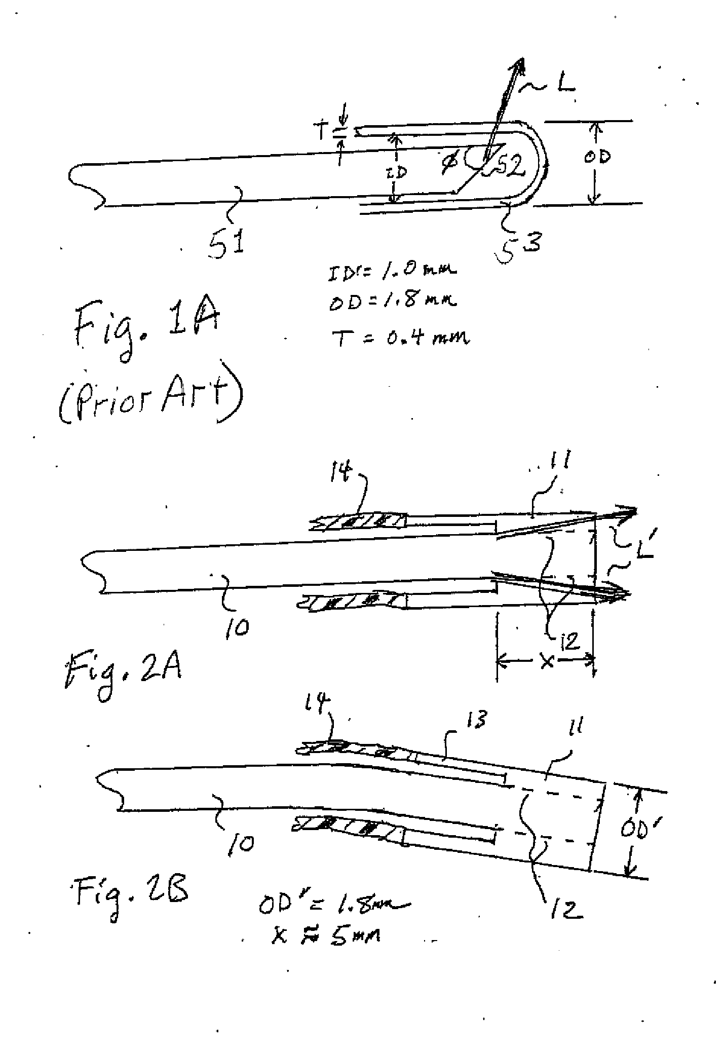
[0024]FIGS. 2A and 2B show an embodiment of the present invention that includes an end-firing optical fiber 10 and a quartz ferrule 11 welded to the distal end of the fiber 10.

[0025]In this embodiment, fiber 10 is preferably sufficiently flexible to enable the fiber to be bent in order to direct laser energy at a desired surface situated to the side of the optical fiber. The ferrule 11 is preferably a quartz ferrule 11 has an index of refraction matched to that of the fiber 10, laser energy L′ disperses to increase the firing angle of the laser.

[0026]The length X of the welded area 12 between the fiber 10 and the ferrule 11 is typically 5 mm or greater. This extended weld gives the fiber 12.5 times greater erosion protection and ensures that the power density will remain high in comparison with a capped fiber arrangement as the power is contained inside the core of the fiber. Those skilled in the art will appreciate that, in this embodiment, the weld can be to the fiber's core or cl...


PUM


Abstract

An end-firing optical fiber includes protective ferrule through which treatment radiation is fired in an axial direction, the protective ferrule having refractive properties that cause the radiation to disperse laterally and/or the fiber having sufficient flexibility to enable the fiber to be aimed at a tissue situated to the side of the axis along which the fiber was inserted. The fiber and protective ferrule may be mounted in a cannula, with the cannula being sufficiently flexible to enable the cannula to be withdrawn into a scope having a straight working channel, but has a pre-formed curvature that enables treatment of lateral tissues when the cannula is extended out of a scope.

Description

[0001]This application claims the benefit of provisional U.S. Patent Application Ser. Nos. 61 / 565,672, filed Dec. 1, 2011, and 61 / 721,104, filed Nov. 1, 2012, each of which is incorporated by reference herein.BACKGROUND OF THE INVENTION[0002]1. Field of the Invention[0003]This invention relates to optical fibers used in laser treatment applications such as, by way of example and not limitation, benign prostate hypertrophy (BPH) treatments.[0004]The invention replaces a side-firing optical fiber surrounded by a protective end cap with one of the following end-firing optical fiber arrangements:[0005](i) an end-firing optical fiber having a protective ferrule welded to the optical fiber, the index of refraction of the ferrule being matched to that of the fiber to cause dispersal of laser energy and increase the firing angle of the laser, or[0006](ii) an end-firing optical fiber and protective ferrule mounted in a cannula, the cannula having a pre-formed curvature that enables treatment...

Claims


Application Information

Patent Timeline
Patent Type & Authority Applications(United States)
IPC IPC(8): A61B18/22
CPCA61B18/22A61B2018/2222A61B2018/2238A61B2018/2272
Inventor BROWN, JOE DENTON
Owner BROWN JOE DENTON
Why Eureka
Try Eureka