
Engine performance modification or tuning kit

a technology for tuning kits and engines, applied in the direction of brake action initiation, braking system, position/direction control, etc., can solve the problems of not being able to make fuel adjustments, engine mapping is often reloaded, and the performance of modern engines can be affected, so as to improve the compatibility of the kit with different engines, the effect of avoiding alarm

Inactive Publication Date: 2013-12-26
MOBILIZER
View PDF56 Cites 10 Cited by
  • Summary
  • Abstract
  • Description
  • Claims
  • Application Information

AI Technical Summary

Benefits of technology

The invention is a kit that allows for adjusting the amount of fuel delivered to an engine based on user requirements. This can be used to enhance engine performance or reduce emissions. The kit can also adapt the fuel delivery map to improve fuel economy or prevent fault conditions. Additionally, the kit can account for latency in the opening of injectors and can handle changes in engine speed or load. The technical effects of the invention revolve around improving engine performance and fuel efficiency while reducing emissions and preventing faults.

Problems solved by technology

However, it is apparent that merely by increasing the ratio of fuel to air, the performance of modern engines can be affected.
A problem with this method is that engine mapping is frequently reloaded by garages when they complete service schedules for a vehicle.
A problem with such a unit is that it is generally not possible to make fuel adjustments at specific engine speeds or loads.
Moreover, the inability to specify under what conditions an increase or decrease in fuel should occur can trigger engine management fault codes or cause drivability issues.
This limits the level of fuel adjustment that can be made.
For example, existing kits that under-report the fuel pressure by, say, 10% or 20%, may be satisfactory at some engine performance levels, but, at others, such substantial change may cause an engine error code to be generated.
Indeed, at low engine loads it is seldom desirable to change the fuel quantity injected.
However, no specific scheme or algorithm is proposed as such.

Method used


Image

  • Engine performance modification or tuning kit
  • Engine performance modification or tuning kit
  • Engine performance modification or tuning kit

Examples


Embodiment Construction

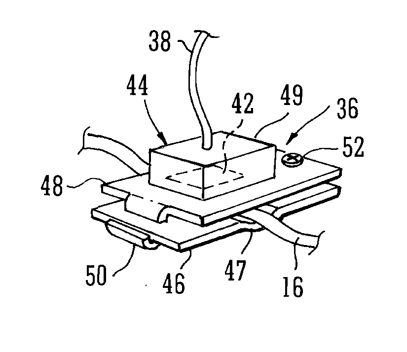
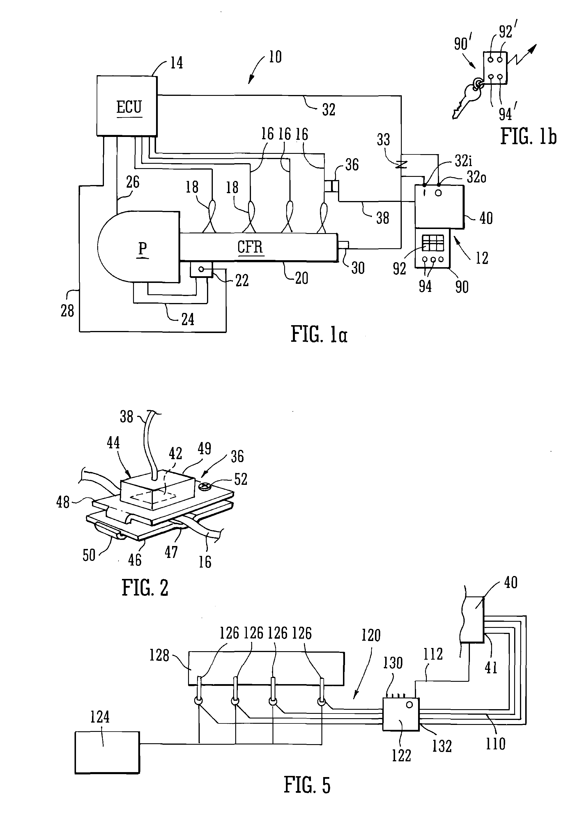
[0071]Referring to FIG. 1, an engine 10 is modified by incorporation of an engine modification kit 12 in accordance with the invention. Engine 10 comprises an engine management control unit (ECU) 14 that sends opening signals along lines 16 to each of a plurality of injectors 18 that are provided, one for each cylinder (not shown) of the engine.

[0072]The injectors 18 are supplied with fuel from a common fuel rail (CFR) 20 that is in turn pressurised by a fuel pump P. The pressure in the fuel rail is controlled by a pressure relief valve 22 that allows fuel to drain from the rail and return to the pump via line 24. Of course, the pressure developed by the pump P is variable and controlled by the ECU along line 26. However, the valve 22 can react much faster to required changes in fuel demand than can the pump itself, and the valve is controlled by the ECU 14 along line 28. The actual pressure developed in the CFR 20 is monitored by a pressure sensor 30, which reports back to the ECU ...


PUM


Abstract

A performance modification / tuning kit for an internal combustion engine of the type comprises a kit control unit. An electrical sensor is adapted to detect the opening and closing signals of a control line to one of the injectors of the engine and connected through a sensor line to the control unit. An input receives the signal from a pressure sensor of the common fuel rail of the engine and an output report a generated pressure signal to the engines ECU. A selectively changeable modification map, comprising modification values for a range of different engine speeds and fuel loads demanded by the ECU is used by the kit control unit to generate the generated pressure signal. That is generated in dependence upon the value in the modification map for the engine fuel load Q currently demanded by the ECU and the engine speed currently pertaining from time to time.

Description

[0001]This invention relates to a tuning kit for modifying the performance of common rail internal combustion engines, in particular, diesel engines.BACKGROUND[0002]A common rail diesel (or petrol) engine has a manifold (the common rail) containing fuel that is under pressure (which pressure is monitored by an engine management unit (ECU)) and a number of injectors supplied by the manifold and connected to each cylinder of the engine. The ECU also controls the injectors and opens each in defined sequence and for controlled periods of time to admit fuel into the engine at the appropriate point(s) of the engine 4-stroke cycle.[0003]The volume of fuel injected in any given engine cycle is obviously a function of the time period that an injector is open during that cycle and the pressure pertaining in the manifold. In fact, it is largely directly proportional to the time, and approximately proportional to the square root of the fuel pressure. The ECU controls the amount of fuel to be in...

Claims


Application Information

Patent Timeline
Patent Type & Authority Applications(United States)
IPC IPC(8): F02D41/26
CPCF02D41/26F02D19/027F02D19/061F02D19/0647F02D19/066F02D41/0027F02D41/3836F02D2041/281F02D2200/0602F02D2200/101F02D2400/11Y02T10/30F02D41/0025F02M63/023
Inventor ZYLA, EDWARDHOWARTH, MARK
Owner MOBILIZER
Learn More