Check patentability & draft patents in minutes with Patsnap Eureka AI!

Method and system for creation of binary spatial filters

a spatial filter and method technology, applied in the field of patterning techniques, can solve the problems of long and expensive procedure for replacing a spatial filter, and achieve the effect of reducing the cost of replacemen

Active Publication Date: 2014-01-02
APPL MATERIALS ISRAEL LTD
View PDF2 Cites 1 Cited by
  • Summary
  • Abstract
  • Description
  • Claims
  • Application Information

AI Technical Summary

Benefits of technology

The present invention provides a solution for designing and implementing spatial filters for use in an inspection system. This allows for on-the-fly and on demand design and production of filters that can be used to filter and mask light from a light source during the inspection process. The invention also includes a method for using total reflection to create a liquid pattern on an optical surface, which can serve as a reference for the desired exposure condition. This setup reduces light absorption and improves the quality of the inspection process.

Problems solved by technology

In such systems, replacement of a spatial filter may be a lengthy and, therefore, also costly procedure.

Method used


Image

  • Method and system for creation of binary spatial filters
  • Method and system for creation of binary spatial filters
  • Method and system for creation of binary spatial filters

Examples


Embodiment Construction

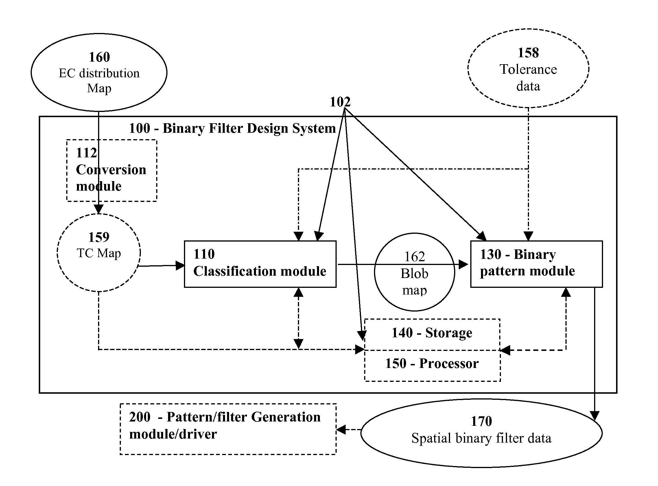
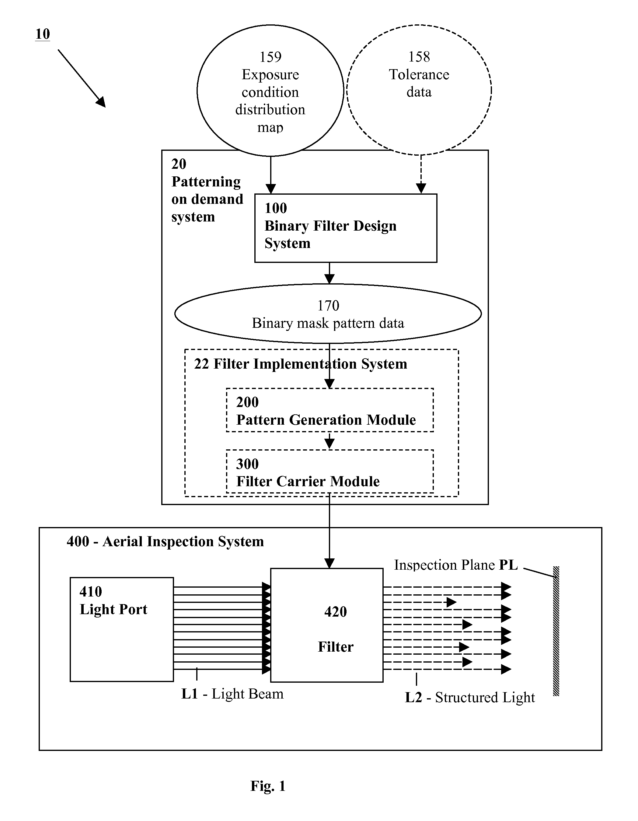
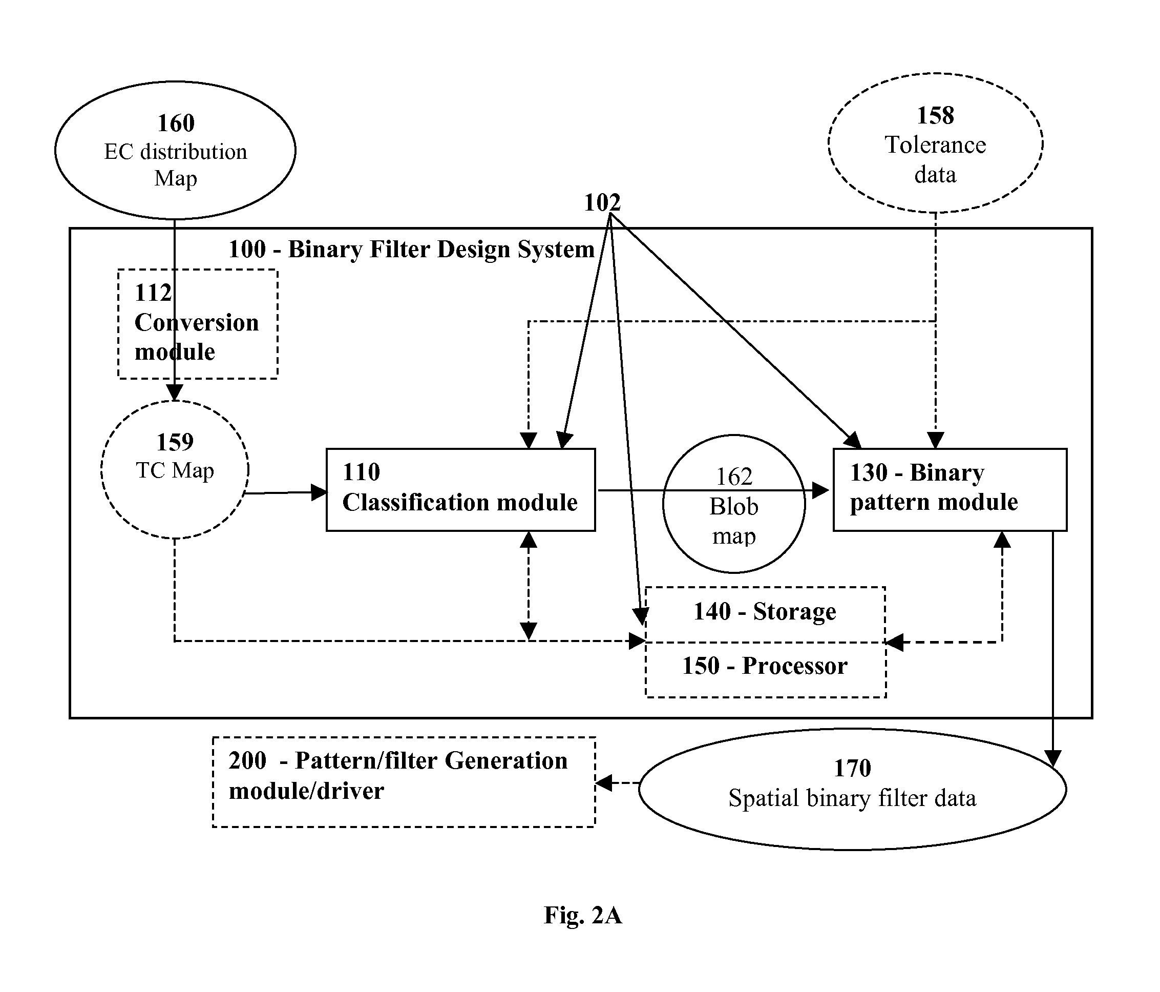
[0049]According to the present invention, methods and systems are provided allowing patterning on demand of binary spatial filters for use in patterning and inspection systems such as aerial imaging and transient generation of such masks. The invention in its one aspect provides a novel binary filter design system, and in some other aspects provides a novel pattern generation system (e.g., mask creation system) which may or may not utilize the binary filter design system. The principles and operation of the present invention may be better understood with reference to the drawings and accompanying description.

[0050]Before explaining exemplary embodiments of the invention in detail, it is to be understood that the invention is not limited in its application to the details of construction and the arrangement of the components set forth in the following description or illustrated in the drawings. The invention is capable of other embodiments or of being practiced or carried out in vario...


PUM


Abstract

Methods and systems for designing a binary spatial filter based on data indicative of a desired exposure condition to be emulated by an inspection system, and for implementing the binary spatial filter in an optical path of the inspection system, thereby enabling emulation of the desired exposure condition by interacting a light beam of the inspection system with the binary spatial filter. The present method and systems enable on-the-fly and on-demand design and implementation / generation of spatial filters for use in inspection systems.

Description

FIELD OF THE INVENTION[0001]The present invention is generally in the field of patterning techniques such as photolithography, and relates to a method and system for creation of binary spatial filters, particularly aimed at optimization of spatial filter formation, e.g., for use in aerial imaging.BACKGROUND OF THE INVENTION[0002]Lithography is a widely used technique for the manufacture of various patterned structures such as integrated circuits, magnetic devices, and other devices. In lithography, a final product is manufactured in a multi-step process, where a “resist” material (sensitive to electromagnetic radiation) is produced for creation of an initial pattern. A pattern is formed in the resist material by exposing different regions of the resist material to different radiation doses. The radiation, e.g., optical radiation in the ultraviolet (UV) or deep UV (DUV) range, or x-rays regimes, is projected through a mask (e.g., reticle) onto the “resist” material.[0003]There are se...

Claims


Application Information

Patent Timeline
IPC IPC(8): G06F17/50
CPCG03F7/70116G03F1/84G01N21/00G01N21/8806G01N21/9501G01N2201/068
Inventor MANGAN, SHMUELSAGIV, AMIRABRAMSON, MARIANO
Owner APPL MATERIALS ISRAEL LTD
Features
  • R&D
  • Intellectual Property
  • Life Sciences
  • Materials
  • Tech Scout
  • Unparalleled Data Quality
  • Higher Quality Content
  • 60% Fewer Hallucinations
Learn More