
Process of using a submerged combustion melter to produce hollow glass fiber or solid glass fiber having entrained bubbles, and burners and systems to make such fibers

a technology of combustion melter and hollow glass fiber, which is applied in the field of combustion furnaces, can solve the problems of turbulence of molten material or partially molten material, and none of the previous solutions have been recognized

Active Publication Date: 2014-01-09
JOHNS MANVILLE CORP
View PDF2 Cites 35 Cited by
  • Summary
  • Abstract
  • Description
  • Claims
  • Application Information

AI Technical Summary

Benefits of technology

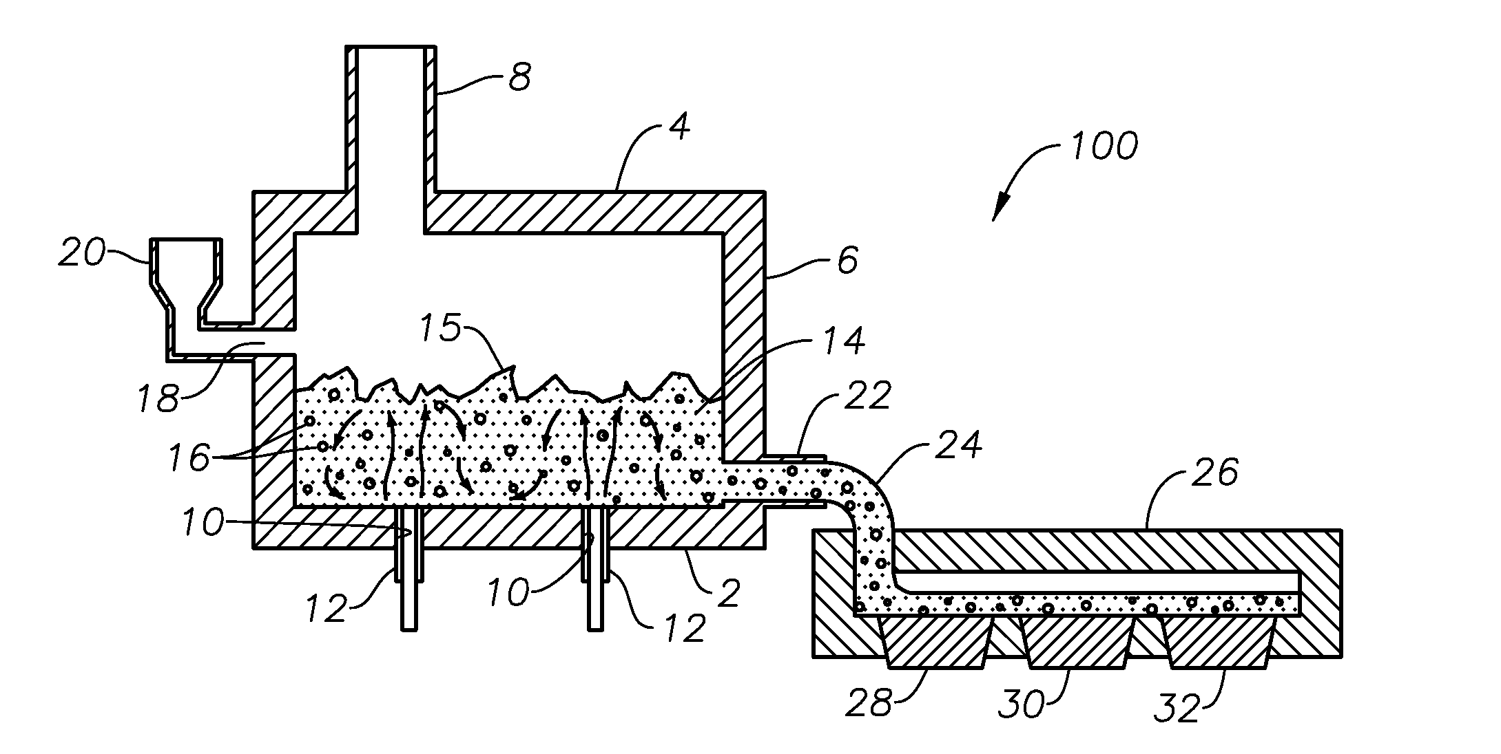
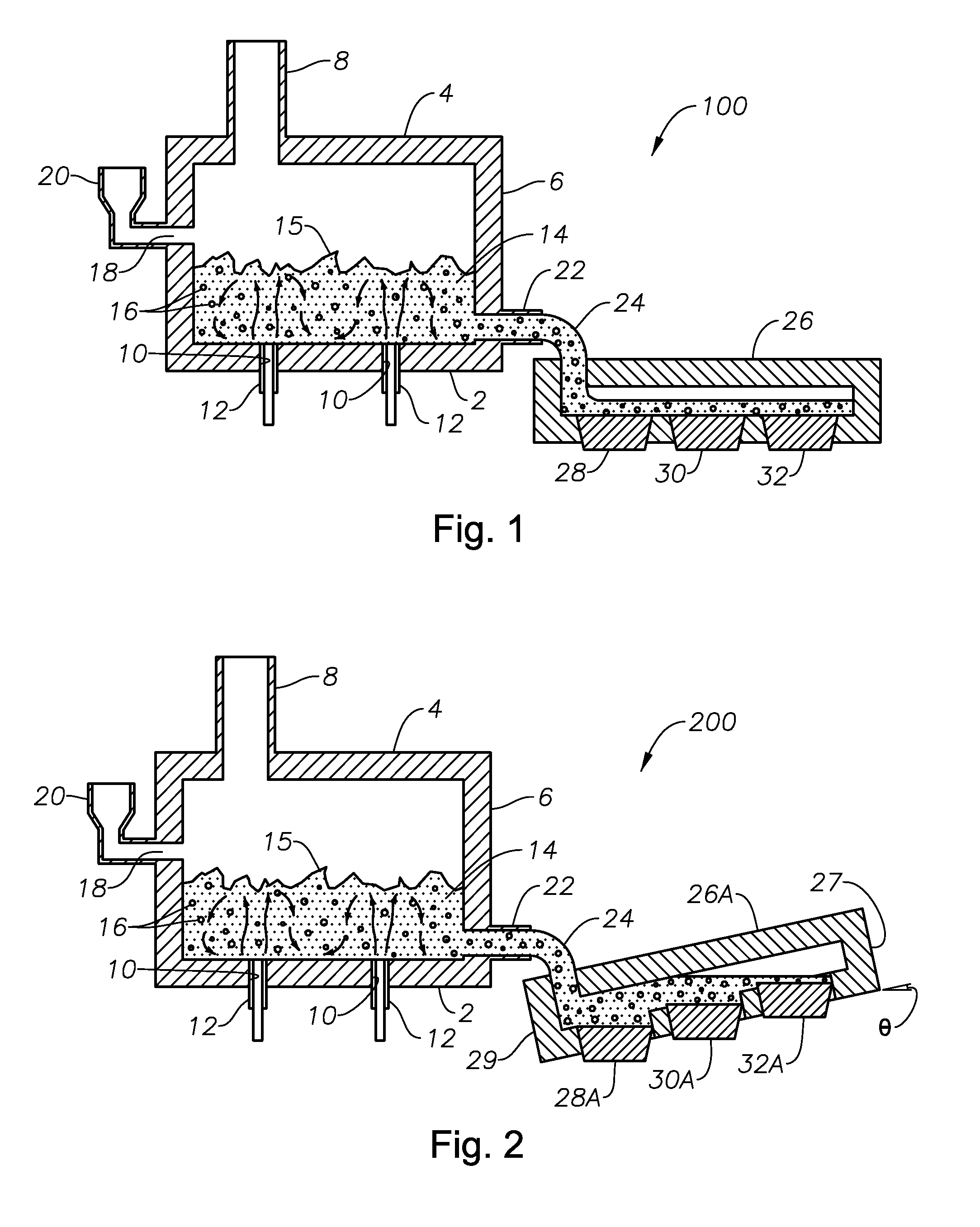
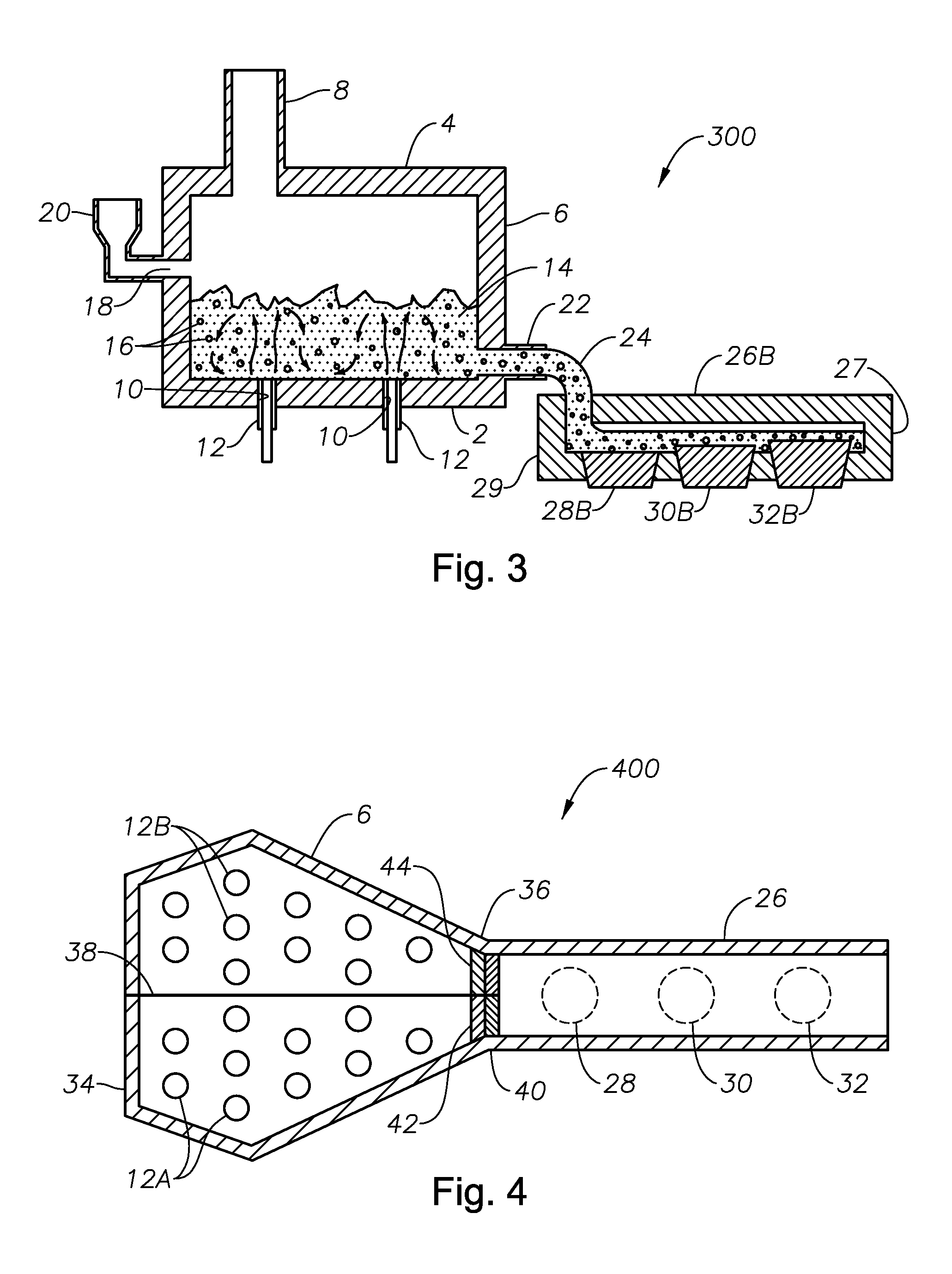
The patent describes a way to control the flow of molten material with bubbles through a device called a forehearth. This helps ensure that the volume of the material is consistent with regions that are free of glass. The technical effect of this is that it improves the production of fibers from the molten material, resulting in a more consistent product.

Problems solved by technology

Using submerged combustion burners produces turbulence of the molten material or partially molten material.
None of the previous solutions have recognized that submerged combustion produces a turbulent molten glass that has approximately 40 percent by volume gas bubbles.
In fact, traditional glass melting technologies seek to reduce bubble content when making glass fibers, as it leads to frequent processing problems due to fiber breakage during drawing.

Method used


Image

  • Process of using a submerged combustion melter to produce hollow glass fiber or solid glass fiber having entrained bubbles, and burners and systems to make such fibers
  • Process of using a submerged combustion melter to produce hollow glass fiber or solid glass fiber having entrained bubbles, and burners and systems to make such fibers
  • Process of using a submerged combustion melter to produce hollow glass fiber or solid glass fiber having entrained bubbles, and burners and systems to make such fibers

Examples


embodiment 700

[0076]As noted herein, in certain embodiments it may be beneficial to inject alternative, non-fuel gas species into molten glass produced by an SCM. One or more tubes or conduits 712, 714 may be provided for this purpose, as illustrated schematically in FIGS. 7 and 7A. Tubes or conduits 712, 714 may terminate near the flow exit of annulus B in ports 713A, 713B, respectively, positioned in primary oxidant conduit 704. Conduits 712, 714 may be positioned in thru-holes 722, 716, respectively, in a first end plate 715. Optional valves 736 may be provided to control and / or adjust flow of alternate gas species through conduits 712, 714. Thru-holes 728, 730 allow a cooling fluid such as water to enter and exit outer annulus A for cooling. One or more valves 740 may be provided to control in-flow of primary fuel. FIG. 7A provides a schematic plan view of apparatus embodiment 700. Of course, more or less than two alternative gas species conduits may be provided, as may more or less than two ...

embodiment 800

[0080]As illustrated in embodiment 800, body 824 may include a circumferential lip 840 that abuts against an overhang portion 815 of end cap 813. End cap 813 has a length or height L1, and lip 840 has a length L2 from overhang portion 815 to upper surface 836 of body 824, where L2 may range from about 0.25 inch to about 2 inches. Circumferential lip extension 840 extends away from upper surface 836 of body 824 and generally parallel to longitudinal axis L1. End cap 813 may extend above exit 825 of the substantially central passage of hub 826 a distance L1, which may range from about 0.5 inch to about 6 inches. Vertical connector section 829 may have a length L3 ranging from about 0.25 inch to about 1 inch. As illustrated in FIG. 8B, exit 825 of the substantially central passage has a diameter L4. L4 may range from about 0.25 inch to about 3.0 inches. Lengths L1, L2, L3, and L4 are parameters that may be changeable and / or adjustable (as those terms are defined herein) in certain embo...


PUM

PropertyMeasurementUnit
angleaaaaaaaaaa
β angleaaaaaaaaaa
angleaaaaaaaaaa

Abstract

Processes and systems for producing glass fibers having regions devoid of glass using submerged combustion melters, including feeding a vitrifiable feed material into a feed inlet of a melting zone of a melter vessel, and heating the vitrifiable material with at least one burner directing combustion products of an oxidant and a first fuel into the melting zone under a level of the molten material in the zone. One or more of the burners is configured to impart heat and turbulence to the molten material, producing a turbulent molten material comprising a plurality of bubbles suspended in the molten material, the bubbles comprising at least some of the combustion products, and optionally other gas species introduced by the burners. The molten material and bubbles are drawn through a bushing fluidly connected to a forehearth to produce a glass fiber comprising a plurality of interior regions substantially devoid of glass.

Description

BACKGROUND INFORMATION[0001]1. Technical Field[0002]The present disclosure relates generally to the field of combustion furnaces and methods of use, and more specifically to processes for producing hollow glass fiber or glass fibers comprising bubbles using a turbulent submerged combustion melter, and burners for carrying out such processes.[0003]2. Background Art[0004]In submerged combustion melting of glass and similar materials, combustion gases emitted from sidewall-mounted and / or floor-mounted burners are injected beneath the surface of a molten or partially molten mass of material being melted in a melter vessel and rise upward through the molten or partially molten mass. The molten or partially molten mass of material is a complex mixture of molten feed material (feed material is commonly referred to as “batch” in the glass industry), unmelted batch, and gases from the burners and evolved gases from the reaction of and / or decomposition of batch materials. Recycled glass or “c...

Claims


Application Information

Patent Timeline
Patent Type & Authority Applications(United States)
IPC IPC(8): C03B37/02F23D14/46F23D14/70C03B37/07
CPCC03B5/2356F23C6/047F23D14/22F23D14/78F23C2201/20F23C2201/301C03B7/02C03B37/075C03B5/193C03B5/2353C03B2203/14C03B2203/16C03B2211/22C03B2211/23C03B2211/40C03B2211/60C03B2201/00C03B37/0756C03B37/022H03F1/3205H03F1/56H03F3/195H03F3/72H03F2200/18H03F2200/21H03F2200/211H03F2200/213H03F2200/222H03F2200/225H03F2200/24H03F2200/243H03F2200/249H03F2200/27H03F2200/294H03F2200/297H03F2200/301H03F2200/306H03F2200/312H03F2200/387H03F2200/391H03F2200/399H03F2200/417H03F2200/451H03F2200/48H03F2200/489H03F2200/492H03F2200/495H03F2200/546H03F2200/75H03G1/0029H03G1/0088H03G1/0094H03G3/001H03G2201/106H03G2201/307H03G2201/504Y02P40/50H03F2200/72H03G3/008H03G3/10C03B37/07F23D14/62
Inventor CHARBONNEAU, MARK WILLIAMMCHUGH, KEVIN PATRICK
Owner JOHNS MANVILLE CORP
Learn More