Thermosiphon Systems for Electronic Devices

a technology of electronic devices and thermosiphon systems, applied in the direction of lighting and heating apparatus, semiconductor/solid-state device details, manufacturing tools, etc., can solve the problem of limited space available in the server rack environment and introduce an additional challenge to the design of thermosiphon systems, and achieve the effect of improving efficiency

Active Publication Date: 2014-01-16
GOOGLE LLC
View PDF26 Cites 39 Cited by
  • Summary
  • Abstract
  • Description
  • Claims
  • Application Information

AI Technical Summary

Benefits of technology

[0007]Several approaches are described, which can be used individually or in combination in order to improve efficiency. A tube with parallel passages can be used to carry the liquid condensate from the condenser to the evaporator and to carry the vapor from the evaporator to the condenser. The evap

Problems solved by technology

Although some systems have been proposed for removing heat from computer components, the limited space a

Method used


Image

  • Thermosiphon Systems for Electronic Devices
  • Thermosiphon Systems for Electronic Devices
  • Thermosiphon Systems for Electronic Devices

Examples


Embodiment Construction

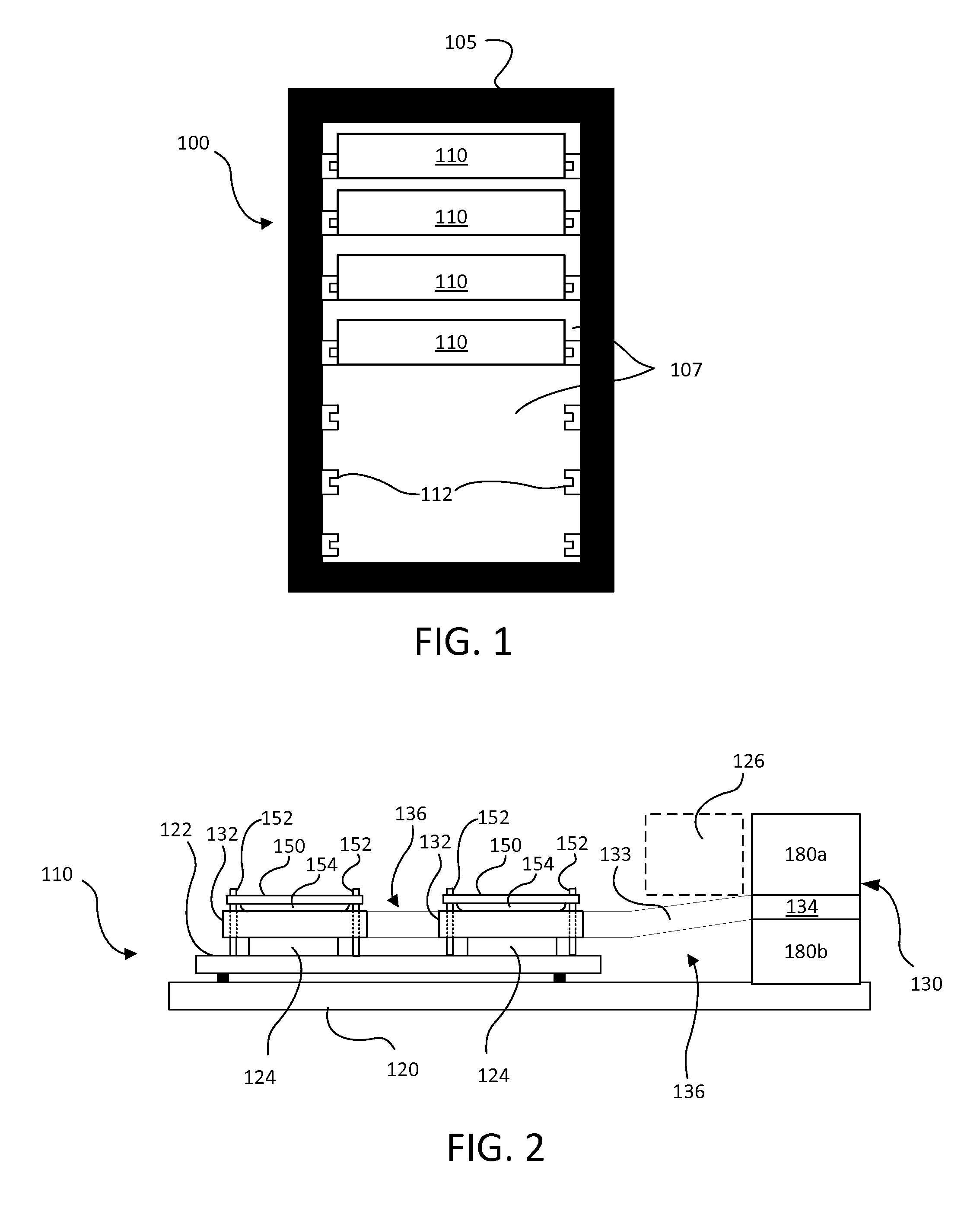
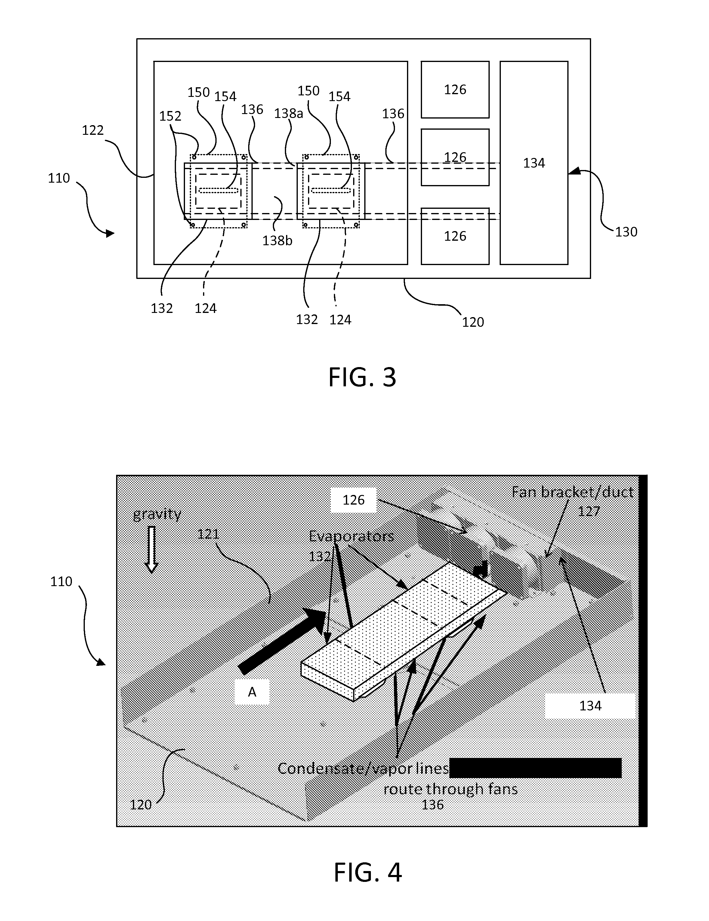
[0039]This document discusses a thermosiphon system that can be implemented to remove heat from an electronic device, e.g., a component of computing equipment, such as a processor or memory. The evaporator of the thermosiphon system contacts the electronic device so that the electronic device experiences a conductive heat transfer effect. Thus, the thermosiphon system can act as a heat sink for the electronic device, reducing the likelihood of overheating and subsequent failure of the electronic device.

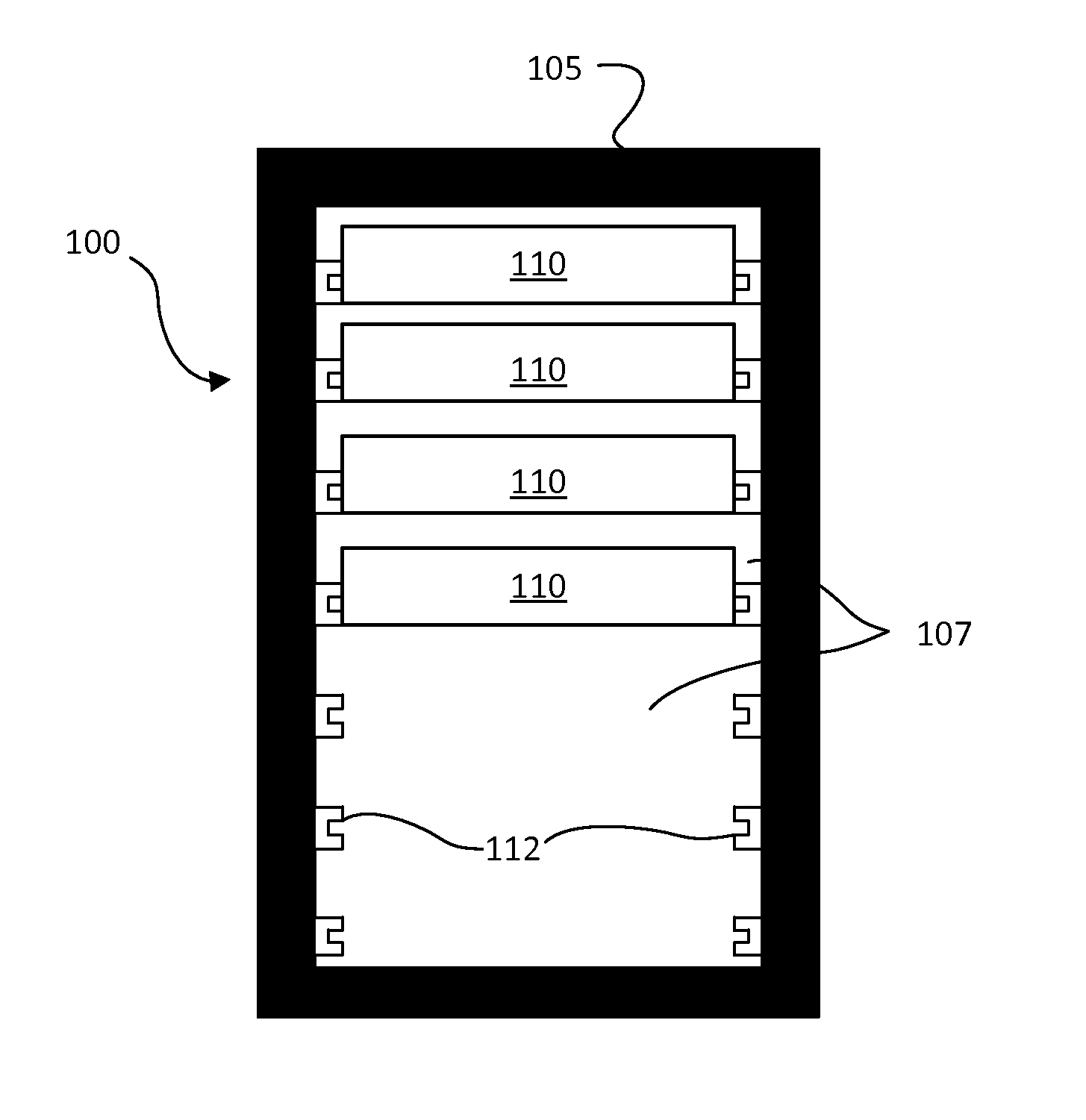
[0040]In particular, the thermosiphon system can be mounted on or integrated with a server rack sub-assembly for insertion into a server rack. The server rack sub-assembly can contain or support a number of heat-generating electronic devices, and the evaporator of the thermosiphon system can contact one or more of the electronic devices. In addition, the thermosiphon system can be mounted on a circuit card assembly, a daughter card, and / or other boards that carry heat-generating elect...


PUM

PropertyMeasurementUnit
Temperatureaaaaaaaaaa
Lengthaaaaaaaaaa

Abstract

A thermosiphon system includes a condenser, an evaporator, and a condensate line fluidically coupling the condenser to the evaporator. The condensate line can be a tube with parallel passages can be used to carry the liquid condensate from the condenser to the evaporator and to carry the vapor from the evaporator to the condenser. The evaporator can be integrated into the tube. The condenser can be constructed with an angled core. The entire assembly can be constructed using a single material, e.g., aluminum, and can be brazed together in a single brazing operation.

Description

TECHNICAL FIELD[0001]This invention relates to thermosiphon systems to remove heat from electronic devices.BACKGROUND[0002]Computer users often focus on the speed of computer microprocessors (e.g., megahertz and gigahertz). Many forget that this speed often comes with a cost—higher power consumption. This power consumption also generates heat. That is because, by simple laws of physics, all the power has to go somewhere, and that somewhere is, in the end, conversion into heat. A pair of microprocessors mounted on a single motherboard can draw hundreds of watts or more of power. Multiply that figure by several thousand (or tens of thousands) to account for the many computers in a large data center, and one can readily appreciate the amount of heat that can be generated. The effects of power consumed by the critical load in the data center are often compounded when one incorporates all of the ancillary equipment required to support the critical load.[0003]Many techniques may be used t...

Claims


Application Information

Patent Timeline
IPC IPC(8): F28D15/02B23P15/26
CPCF28D15/0266F28D15/0275F28F1/40H01L23/367H01L23/4006H01L23/427H05K7/20809F28F2013/006H01L2023/4087H01L2023/4081H01L2924/0002H01L2924/00Y10T29/49393H01L23/3675B23P15/26
Inventor RICE, JEREMYSPAULDING, JEFFREY S.NGUYEN, HUAN D.
Owner GOOGLE LLC
Why Eureka
Try Eureka