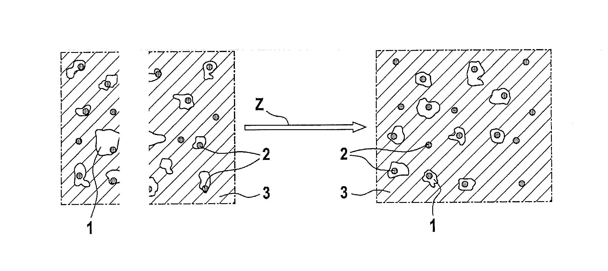
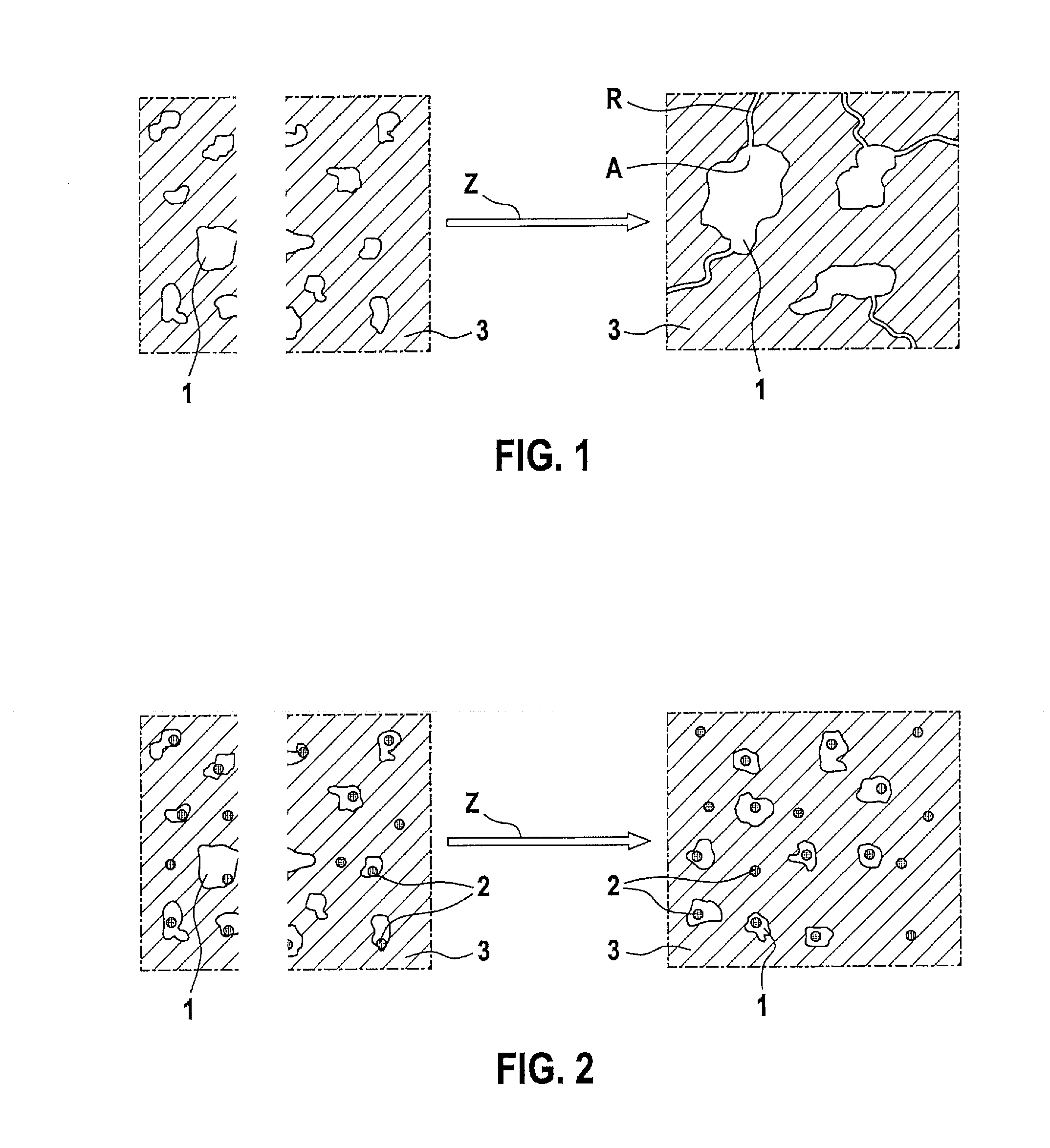
Cathode composition

a technology of cathode composition and alkali sulfur, which is applied in the direction of non-metal conductors, cell components, conductors, etc., can solve the problem of typical only achieving a cycle number, and achieve the effect of reducing the formation of sulfur agglomerates advantageously

Inactive Publication Date: 2014-01-16
ROBERT BOSCH GMBH
View PDF2 Cites 10 Cited by
  • Summary
  • Abstract
  • Description
  • Claims
  • Application Information

AI Technical Summary

Benefits of technology

[0013]Within the scope of another specific embodiment, the sulfur, of the sulfur composite material is provided homogeneou

Problems solved by technology

However, such cells typically only achiev

Method used


Image

  • Cathode composition
  • Cathode composition

Examples


example 1

Manufacturing of a Sulfur-Polyacrylonitrile Composite Material

[0043]15 g elementary sulfur and 5 g polyacrylonitrile were mixed and heated to 330° C. for 6 hours. The sulfur-polyacrylonitrile composite material thus manufactured had 40 wt.-% sulfur.

example 2

Manufacturing of a Cathode Composition

[0044]5 g elementary sulfur and 1 g of the sulfur-polyacrylonitrile composite material from Example 1 were stirred together with N-methyl-2-pyrrolidinone (NMP) in a SpeedMixer at 10,000 RPM for 20 minutes. 1 g carbon black (Super-P Li from Timcal) was then added. After a further 20 minutes of stirring time, 1 g graphite and 2 g PVDF were added. The mixture was stirred for a further 120 minutes.

example 3

Manufacturing of a Cathode

[0045]The mixture from example 2 was applied using a coating knife to an aluminum foil. The cathode was then dried for two hours at 60° C. on a heating plate. The assembly was subsequently transferred into a vacuum furnace and dried for a further 12 hours at 60° C.

[0046]The resulting cathode was installed in a lithium-sulfur cell. The lithium-sulfur cell thus manufactured had a homogeneous sulfur distribution during the charging procedure.


PUM


Abstract

A cathode composition for an alkali-sulfur cell, e.g., a lithium-sulfur cell, includes, in addition to elementary sulfur, at least one material having covalently and/or conically bound sulfur, for example, a sulfur composite material, a sulfurous polymer, a metal sulfide, or a nonmetal sulfide.

Description

BACKGROUND OF THE INVENTION[0001]1. FIELD OF THE INVENTION[0002]The present invention relates to a cathode composition for an alkali-sulfur cell, in particular a lithium-sulfur cell, a manufacturing method for a cathode for an alkali-sulfur cell, and a corresponding cathode and alkali-sulfur cell.[0003]2. DESCRIPTION OF THE RELATED ART[0004]In order to be able to achieve ranges of greater than 200 km using an electric vehicle with acceptable battery weight, research is continuously being made for novel battery materials and technologies. Lithium-sulfur cells represent a promising candidate for this purpose. Sulfur is reduced to form lithium sulfide via polysulfides during the discharge in lithium-sulfur cells. Vice versa, oxidation of the sulfide to form sulfur occurs during the charging of the cell. Presently, energy densities of up to 350 Wh / kg may be achieved using lithium-sulfur cells. However, such cells typically only achieve a cycle number of just over 100 cycles.BRIEF SUMMAR...

Claims


Application Information

Patent Timeline
IPC IPC(8): H01M4/60H01M4/04H01M4/38
CPCH01M4/602H01M4/38H01M4/0402H01M4/0404H01M4/136H01M4/137H01M4/1397H01M4/364H01M4/581H01M4/5815H01M4/60H01M4/604H01M4/622H01M4/625H01M10/052H01M2004/028Y02E60/10
Inventor WEGNER, MARCUSTOMFORDE, JANHASENKOX, ULRICHGRIMMINGER, JENSTENZER, MARTINLIEDTKE, RALF
Owner ROBERT BOSCH GMBH
Why Eureka
Try Eureka