Charged particle beam apparatus

a charge-pulverized particle and beam technology, applied in the direction of beam deviation/focusing by electric/magnetic means, instruments, mass spectrometers, etc., can solve the problems of difficult to separate the tilt angle and the generated aberration from each other, and achieve the effect of simple structur

Active Publication Date: 2014-01-23
HITACHI HIGH-TECH CORP
View PDF0 Cites 10 Cited by
  • Summary
  • Abstract
  • Description
  • Claims
  • Application Information

AI Technical Summary

Benefits of technology

[0015]A charged particle beam apparatus aiming to correct both of the off-axis chromatic aberration and the deflection coma aberration by a relatively simple structure is proposed below.
[0017]According to the above structure, it becomes possible to provide a charged particle beam apparatus having a simple structure which can suppress the off-axis chromatic aberration and the deflection coma aberration.

Problems solved by technology

Therefore, if there is another factor, such as the axis deviation or the assembling error of the objective lens, which causes a deviation from the ideal compensation state, it is difficult to comply with varying aberration compensation conditions.
Further, it is difficult to separate the tilt angle and the generated aberration from each other.
Therefore, when a large angle tilting (tilt angle of 10 degrees or more) is performed according to this technique, the deflection coma aberration becomes apparent and the resolution might be degraded.
Therefore, the compensation unit shape and the number of power supplies for the electrode control increase, and control becomes complex.
This system considers beam tilting as an extension of the on-axis aberration and can make the aberration correction in all directions but can not avoid from having a correction unit formed of multiple stages and a multipole.

Method used


Image

  • Charged particle beam apparatus
  • Charged particle beam apparatus
  • Charged particle beam apparatus

Examples


first embodiment

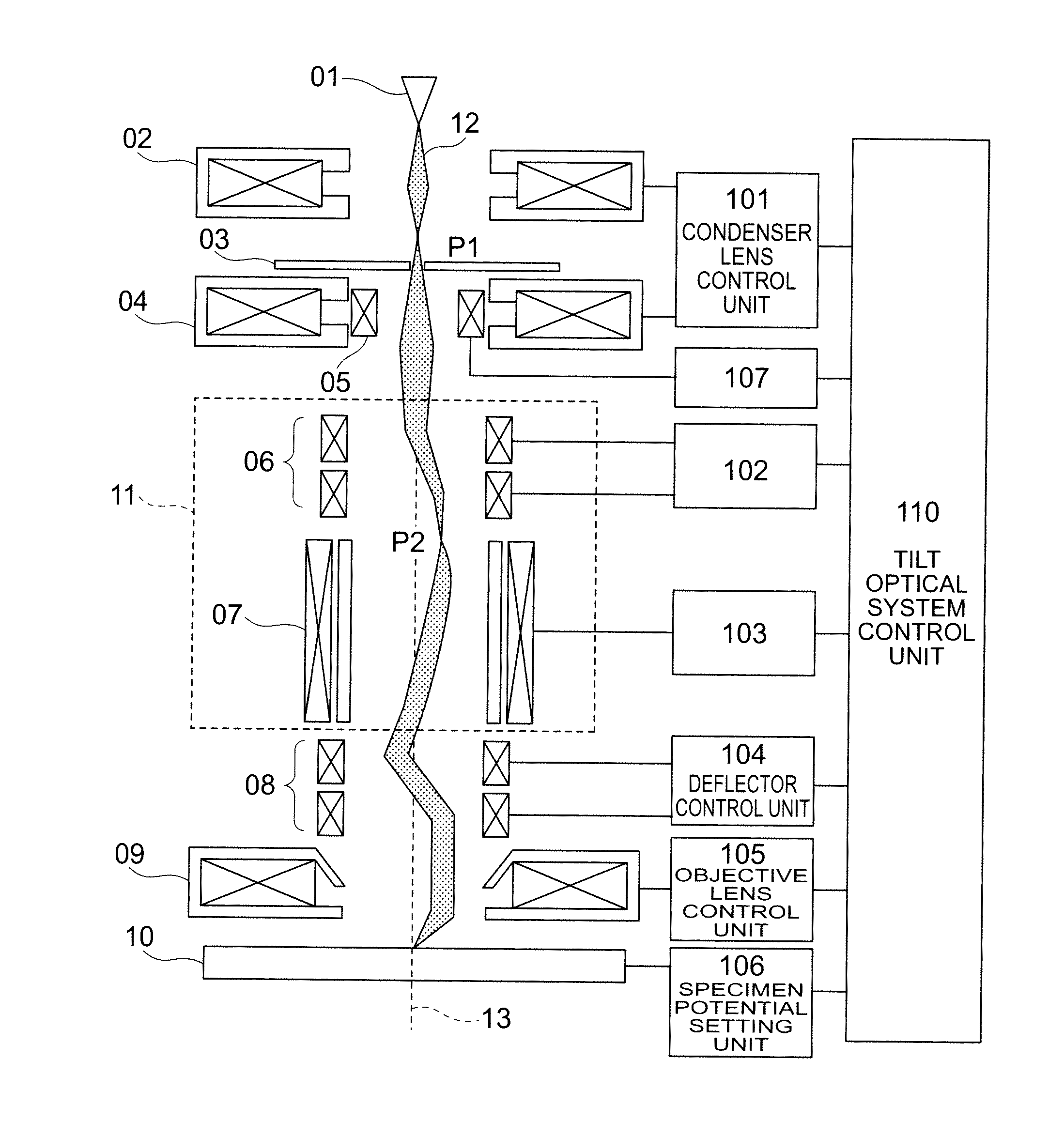
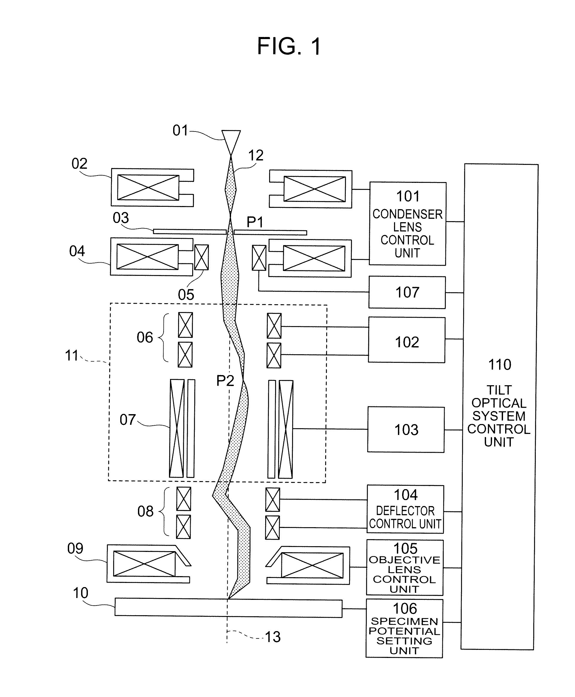
[0039]Embodiments are described in detail below with reference to the drawings. The structure of the first embodiment is shown in FIG. 1, a flowchart is shown in FIG. 4, and details of a tilt optical system control unit 110 are shown in FIG. 5. In Step 001, excitation conditions for each lens and a specimen potential are given to a condenser lens control unit 101, an objective lens control unit 105 and a specimen potential setting unit 106 and set by the tilt optical system control unit 110. (In this embodiment, as an excitation amount of the condenser lens 04, P2 is explained referring to the conditions determined at the Wien filter inlet, but an aberration for correcting can be generated by the aberration correction unit 11 on the same principle even when P2 is set at another place in order to adjust the aperture angle and the current amount.) The tilt angle of the beam is set in Step 002. At this time, current for operating a deflection coil 8 according to the tilt angle is appli...

second embodiment

[0046]In Step 009, distortion aberration generated in the aberration correction unit 11 is corrected by the two-stage deflector 08. Details of the correction method are described in a In Step 010, the beam is tilted with superimposing the correction amount of the distortion aberration determined in Step 009 on the deflection coil 08. In Step 011, an SEM image when the beam was tilted is obtained.

[0047]In Step 012, a tilt image of the beam is obtained, and it is judged if a desired sharpness degree was obtained from the sharpness degree of the image. If the desired sharpness degree was not obtained, the process returns to Step 007 to give a new Δrp2.

[0048]In this embodiment, the operation condition stored in the operation condition recording units (211, 212 and 213) are used when the beam is tilted, so that the adjustment procedure performed when the beam is tilted can be made simple.

[0049]As the second embodiment, a method of correcting the distortion aberration generated by the co...

third embodiment

[0055]As a third embodiment, description is made on a beam tilt optical system which can simultaneously generate a dispersion and coma aberration when another stage of the Wien filter is added instead of the deflector 06 without giving a change of entry position Δrp2 to the Wien filter 07.

[0056]FIG. 7 shows a structure diagram of the beam tilt optical system according to this embodiment. The aberration correction unit 11 of the beam tilt optical system shown in the first and second embodiments is comprised of a combination of the deflector and the Wien filter, but an aberration correction unit 14 according to this embodiment has a feature that it is comprised of a two-stage Wien filter.

[0057]Features of the aberration correction unit 11 and the aberration correction unit 14 are described. When the primary electrons 12 pass through the Wien filter 07 which is disposed in the aberration correction units (11 and 14), opening components (∝α*2 and ∝αα*) of the secondary aberration are ge...


PUM


Abstract

The present invention provides a charged particle beam apparatus which is provided with a tilting deflector which is disposed between a charged particle source and an objective lens and tilts a charged particle beam, wherein a first optical element includes an electromagnetic quadrupole which generates dispersion to suppress the dispersion which is generated by deflection by the tilting deflector, and a second optical element is composed of a deflector for deflecting the charged particle beam which enters the first optical element or an electromagnetic quadrupole which causes the charged particle beam to generate a dispersion different from the dispersion generated by the first optical element.

Description

BACKGROUND OF THE INVENTION[0001]The present invention relates to a charged particle beam apparatus such as a scanning electron microscope, and more particularly to a charged particle beam apparatus which tilts and emits a beam with respect to a specimen or to an ideal optical axis of the beam.[0002]An inspection device and a measuring device using an electron beam are demanded to have high precision three-dimensional observation function in order to improve a yield of a three-dimensional device. A method of obtaining an image with a stage inclined has been used for three-dimensional observation using an electron microscope. However, it had problems that the reproducibility of throughput and tilt angle was degraded because mechanical movement was needed to tilt a stage or a column. A method is considered to use a deflector to tilt the beam in order to perform a three-dimensional measurement of the device without inclining the stage.[0003]However, when beam tilt (deflection) is perfo...

Claims


Application Information

Patent Timeline
Patent Type & Authority Applications(United States)
IPC IPC(8): H01J3/26H01J3/14
CPCH01J3/26H01J3/14H01J37/28H01J37/1478H01J37/153H01J2237/1501H01J2237/1508
Inventor DOHI, HIDETOIKEGAMI, AKIRAKAZUMI, HIDEYUKI
Owner HITACHI HIGH-TECH CORP
Why Eureka
Try Eureka