Gas Analyzer

Active Publication Date: 2014-01-23
SHIMADZU CORP
View PDF1 Cites 8 Cited by
  • Summary
  • Abstract
  • Description
  • Claims
  • Application Information

AI Technical Summary

Benefits of technology

The present invention is a gas analyzer that can detect the pressure and temperature of a gas using a laser beam. It can measure the absorption spectrum of the gas and determine if it falls within a high-vacuum region based on the pressure and temperature. This eliminates the need for a pressure sensor, reducing the cost and size of the device. Additionally, if the pressure and temperature are known, the gas analyzer can detect abnormalities in either the pressure or temperature of the gas. Consequently, the gas analyzer is more efficient and cost-effective for detecting abnormalities in gas pressure and temperature.

Problems solved by technology

However, with a configuration wherein a gas temperature sensor or a pressure sensor is not provided, rapid changes in pressure or temperature of the gas to be measured caused by some abnormality in the measurement environment will go undetected, raising the risk that an erroneous partial pressure value will be output as the correct measurement result.
However, pressure sensors and gas temperature sensors are generally not inexpensive, and they occupy physical space.

Method used


Image

  • Gas Analyzer
  • Gas Analyzer
  • Gas Analyzer

Examples


embodiment 1

[0046]A first embodiment of a gas analyzer according to the present invention as a moisture measurement apparatus is described next with reference to figures.

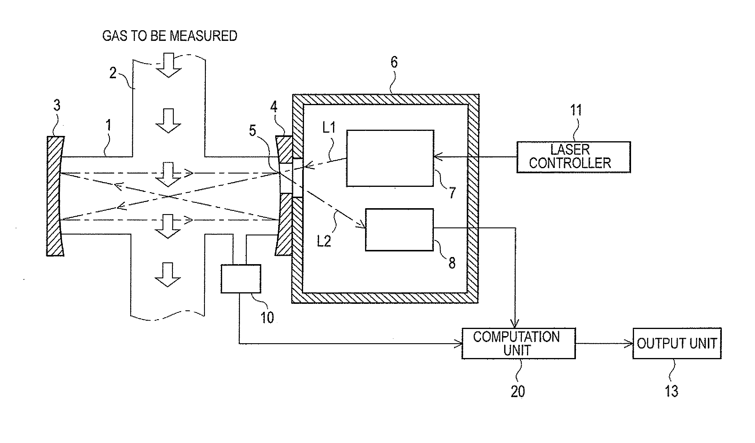
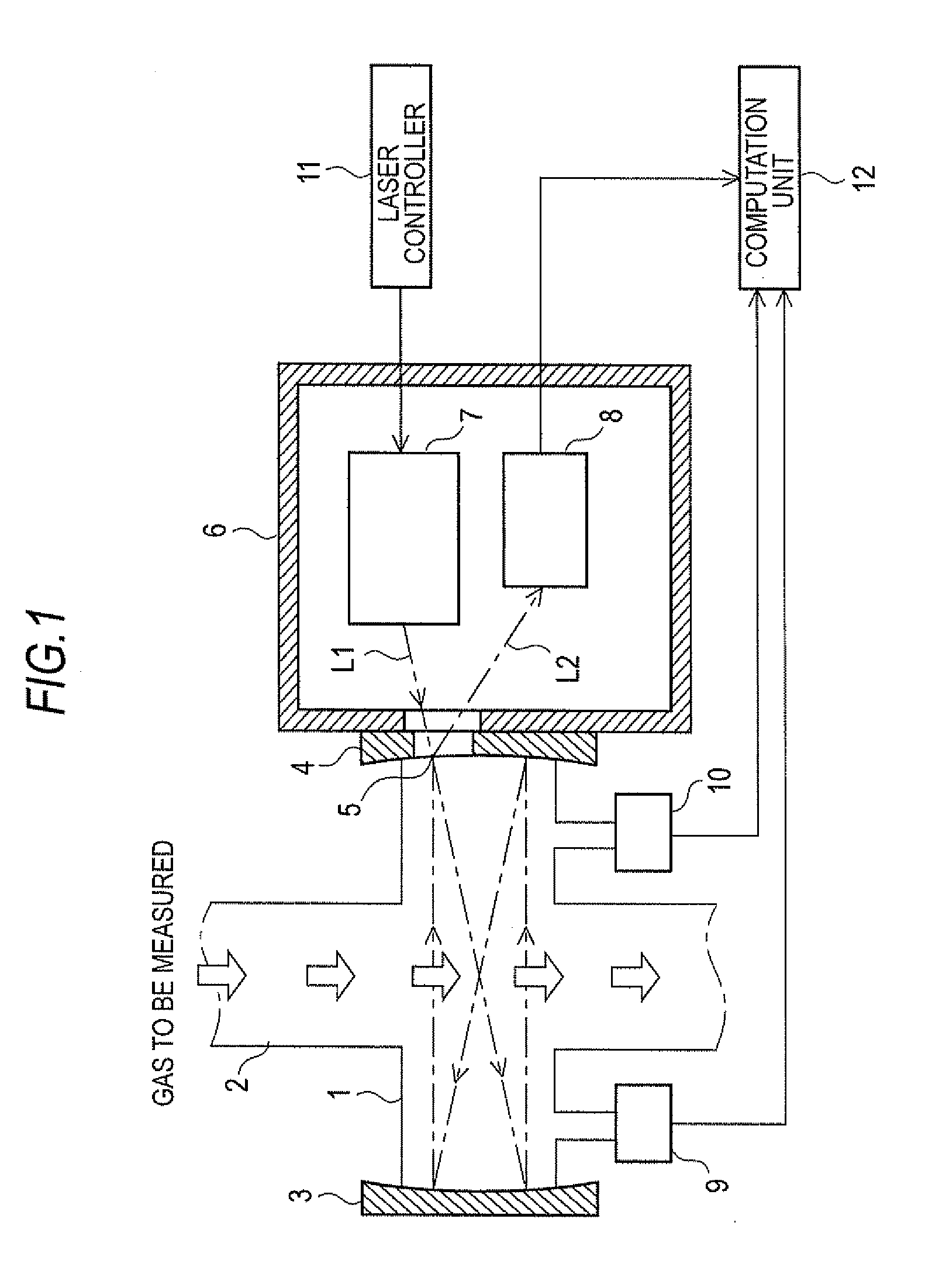
[0047]FIG. 3 shows a schematic view of the present embodiment as a moisture measurement apparatus. The measurement optical system of the moisture measurement apparatus is the same as that described above for a gas measurement apparatus of the previous type shown in FIG. 1. In other words, the measurement optical system includes a gas flow path 2 through which the gas to be measured flows, a sample cell 1 that is positioned in gas flow path 2 to be substantially orthogonal to the direction of gas flow path 2, reflection mirrors 3 and 4, which oppose each other that are disposed at either ends of sample cell 1, a transparent window 5 through which only light can pass that is disposed on reflection mirror 3, an optical chamber 6 with a substantially sealed structure and whose atmosphere is at substantially atmospheric pressure tha...

embodiment 2

[0066]The afore-described embodiments were capable of notifying to the outside of just abnormalities that are detected when the amount of spread W does not fall within a predetermined range. In doing this, it is also possible to configure the device to calculate the pressure of the gas to be measured from the measured values of temperature and the amount of spread and to output the results to an output unit 13. This is explained with reference to the block diagram shown in FIG. 10 and the flowchart shown in FIG. 11.

[0067]The configuration of the moisture measurement apparatus of this embodiment is the same as that of the first embodiment shown in FIG. 3 except for the fact that the computation unit 20 is replaced by computation unit 20A shown in FIG. 10. The configuration of computation unit 20A is the same as that of computation unit 20 except for the new addition of a total pressure calculation unit 25.

[0068]The specific processing procedure that is used by computation unit 20A in...

embodiment 3

[0071]The first and second embodiments of the gas analyzers according to the present invention can also be used as a vacuum level determination device for determining the level of vacuum inside sample cell (measurement space) 1. The configuration of the vacuum level determination device of this embodiment is substantially the same as that of the first and second embodiments of the gas analyzer except for the elimination of partial pressure measurement unit 24 from the configuration of computation unit 20 or 20A as shown in FIG. 13(a) showing computation unit 20C or FIG. 13(b) showing computation unit 20D. The vacuum level determination device is capable of constantly monitoring, in a non-contact manner and with a high time resolution, whether or not the pressure within a sample cell (measurement space) 1 falls within a predetermined high-vacuum region.


PUM


Abstract

A gas analyzer is capable of detecting abnormality of a measurement environment without using either or both of a pressure sensor and a gas temperature sensor. The gas analyzer creates absorption spectra from transmitted light intensity of laser beams applied to gas for measuring the amount of spread W and compares the amount of spread against a threshold D. The amount of spread of the absorption spectra does not depend on pressure if the pressure of the gas to be measured falls within a high-vacuum region, and monotonously increases with increased pressure if the pressure of the gas to be measured is higher than the high-vacuum region. Thus, if W>D, it is determined that the measurement environment does not form a high-vacuum region and abnormality is transmitted to the outside. In all other cases, the measurement environment is deemed to form a high-vacuum region, and partial pressure is calculated.

Description

TECHNICAL FIELD[0001]The present invention relates to a gas analyzer that uses laser absorption spectroscopy for measuring the partial pressure of a specific gas in a gas to be measured.BACKGROUND ART[0002]A method for measuring the partial pressure of a specific gas in a gas to be measured that has been proposed in recent years is laser absorption spectroscopy that uses a wavelength variable laser (see, for example, Patent Literature 1). With this method, a sample cell into which a gas to be measured has been introduced is irradiated with a laser beam while changing its wavelength within a predetermined wavelength range. The laser beam that has been transmitted through the gas to be measured is analyzed, and a partial pressure of a specific gas is calculated from the amount of absorption by the specific gas in the gas to be measured. Because there is no contact between the gas to be measured and the light source or the photoreceptors, this device offers advantages such as measureme...

Claims


Application Information

Patent Timeline
IPC IPC(8): G01J3/02
CPCG01J3/42G01N21/3504G01N21/39G01N21/61G01N21/85
Inventor OTERA, FUMIAKI
Owner SHIMADZU CORP
Why Eureka
Try Eureka