Device and Method for Manufacturing Semi-Carbonized Fuel of Biomass, and Power Generation System Using Semi-Carbonized Fuel

a technology of biomass and semi-carbonized fuel, which is applied in the direction of waste based fuel, solid fuel combustion, lighting and heating apparatus, etc., can solve the problems of increasing transportation costs, reducing calorific value, and using biomass as solid fuel, and achieves the effect of suppressing the adhesion of tar and condensed water

Active Publication Date: 2014-01-30
MITSUBISHI POWER LTD
View PDF6 Cites 11 Cited by
  • Summary
  • Abstract
  • Description
  • Claims
  • Application Information

AI Technical Summary

Benefits of technology

[0018]The device and the method for manufacturing a semi-carbonized fuel of a biomass according to the present invention do not require an external heat source and are capable of suppressing adhesion of tar, condensed water or the like to a pipe.

Problems solved by technology

There are two main problems in the use of the biomass as the solid fuel.
If the water content is high, there are disadvantages of decrease in calorific value, increase in transportation cost, and further, increase in possibility of spontaneous combustion due to the progression of microbial actions.
Therefore, the biomass is not suitable for long-distance transportation and long-term storage.
Another problem is that the crushability is poor since the major constituent is formed of fiberous materials.
However, since the biomass is soft compared to coal and contains large amounts of fiberous materials, the pulverization thereof is difficult to be achieved by the compression milling method described above, and the crushing efficiency indicating the degree of atomization with respect to the required power is low.
Therefore, it has been difficult to achieve mass pulverization similarly to coal.

Method used


Image

  • Device and Method for Manufacturing Semi-Carbonized Fuel of Biomass, and Power Generation System Using Semi-Carbonized Fuel
  • Device and Method for Manufacturing Semi-Carbonized Fuel of Biomass, and Power Generation System Using Semi-Carbonized Fuel
  • Device and Method for Manufacturing Semi-Carbonized Fuel of Biomass, and Power Generation System Using Semi-Carbonized Fuel

Examples


first embodiment

[0044]Hereinafter, a device for manufacturing a semi-carbonized fuel of a biomass according to the first embodiment of the present invention will be described.

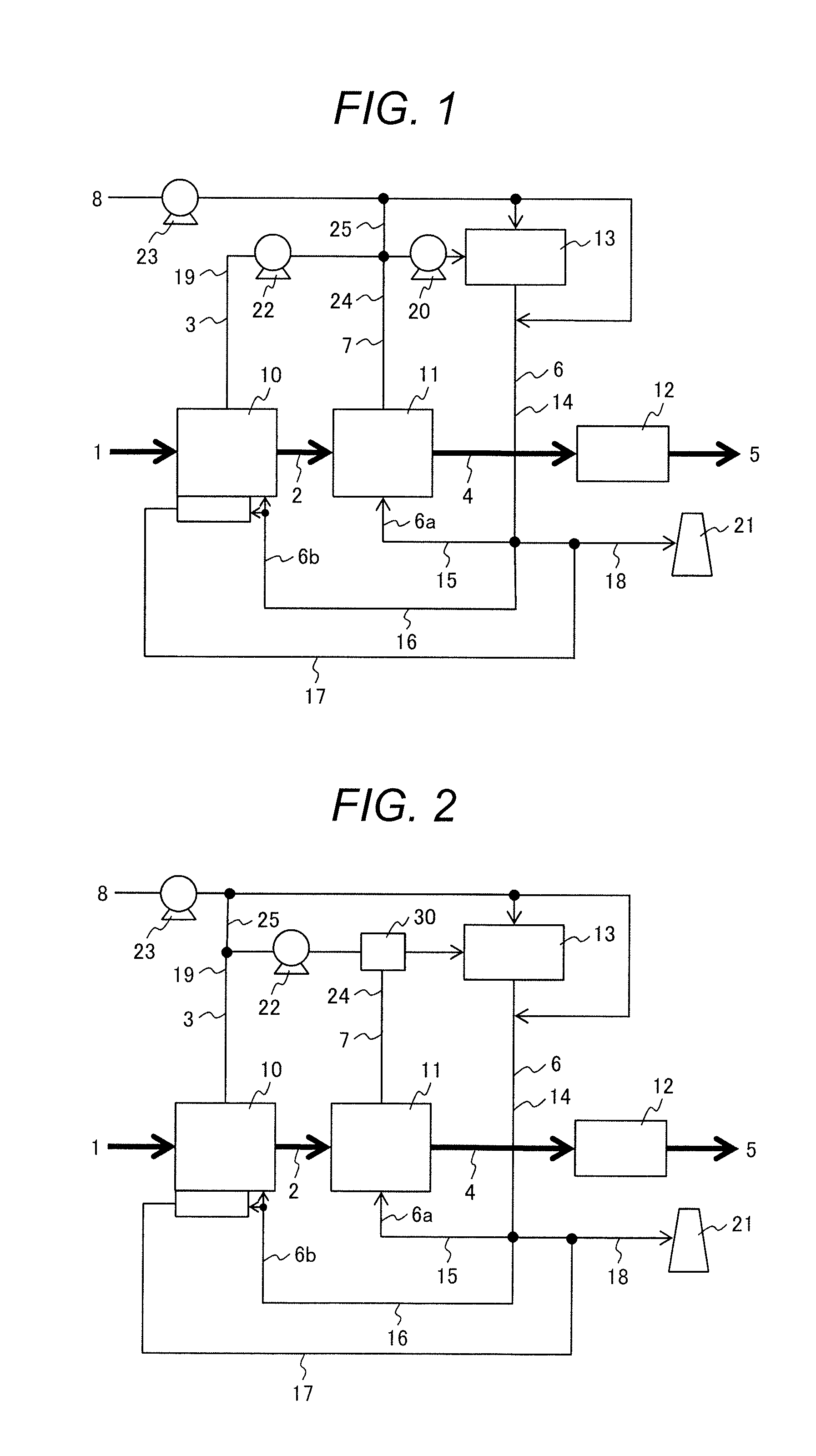
[0045]FIG. 1 is a configuration diagram of the device for manufacturing the semi-carbonized fuel of the biomass according to the first embodiment. The manufacturing device includes a drying device 10, a pyrolysis device 11, a pellet manufacturing device 12, a combustion device 13, and a chimney 21 as major component devices. These devices are connected to each other by ducts 14 to 19, 24, and 25. In FIG. 1, out of the lines connecting the devices, thick lines indicate the flow of solid materials originating from the raw biomass, and thin lines indicate the flow of gas components such as air and the exhaust gas.

[0046]Raw biomass 1 composed of plant wastes such as chaff, straw, thinned wood, and waste wood is heated and dried in the drying device 10 into dried biomass 2 from which moisture is separated, and a gas component (here...

second embodiment

[0064]Hereinafter, a device for manufacturing a semi-carbonized fuel of a biomass according to the second embodiment of the present invention will be described.

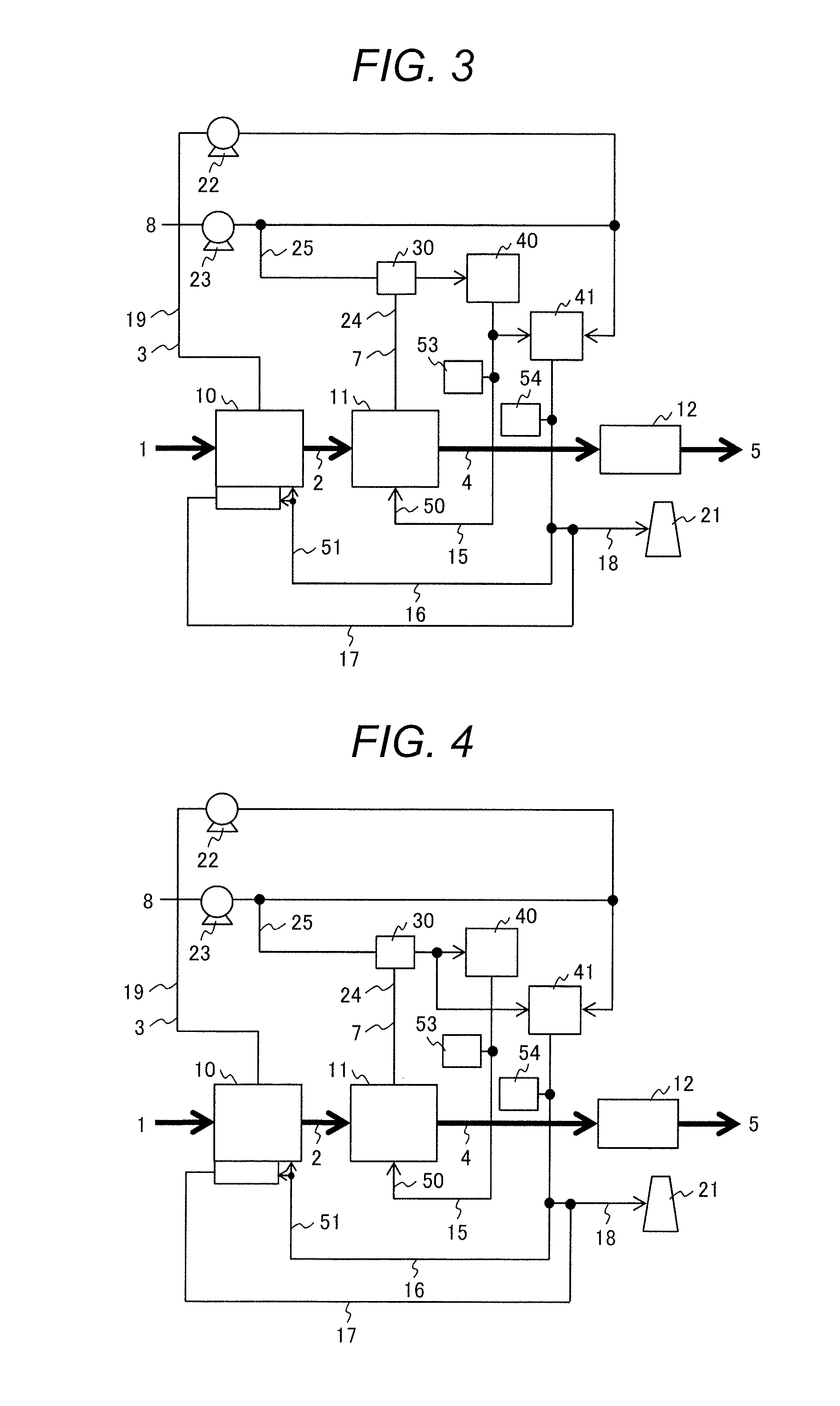
[0065]FIG. 2 is a configuration diagram of the device for manufacturing the semi-carbonized fuel of the biomass according to the second embodiment. In FIG. 2, the same reference characters as in FIG. 1 denote the elements same as or common to those of the first embodiment, and the explanation regarding these elements will be omitted. In FIG. 2, out of the lines connecting the devices, thick lines also indicate the flow of the solid materials originating from the raw biomass, and thin lines also indicate the flow of the gas components such as air or the exhaust gas. Further, the supplying equipment related to the transportation of the solid materials, the damper used to regulate the flow rate of the gas components, and so on are omitted in FIG. 2. Although not shown in FIG. 2, it is also possible to provide a system for supply...

third embodiment

[0071]Hereinafter, a device for manufacturing a semi-carbonized fuel of a biomass according to the third embodiment of the present invention will be described.

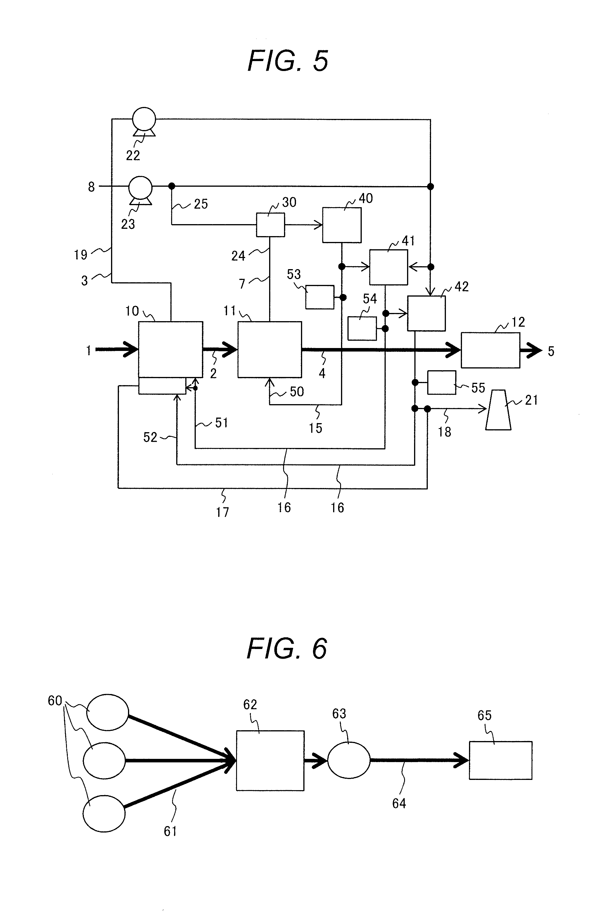
[0072]FIG. 3 is a configuration diagram of the device for manufacturing the semi-carbonized fuel of the biomass according to the third embodiment. In FIG. 3, the same reference characters as in FIG. 2 denote the elements same as or common to those of the second embodiment, and the explanation regarding these elements will be omitted. In FIG. 3, out of the lines connecting the devices, thick lines also indicate the flow of the solid materials originated from the raw biomass, and thin lines also indicate the flow of the gas components such as air or the exhaust gas. Further, the supplying equipment related to the transportation of the solid materials, the damper used to regulate the flow rate of the gas components, and so on are omitted in FIG. 3. Although not shown in FIG. 3, it is also possible to provide a system for supplyin...


PUM

PropertyMeasurementUnit
temperatureaaaaaaaaaa
water contentaaaaaaaaaa
temperatureaaaaaaaaaa

Abstract

Provided are a device and a method for manufacturing a semi-carbonized fuel of a biomass that does not require an external heat source and is capable of suppressing adhesion of tar, condensed water, or the like to a pipe. The device includes a drying device for heating and drying a biomass, a pyrolysis device for decomposing the dried biomass, and a combustion device for supplying heat to the drying device and the pyrolysis device. The pyrolysis device is supplied with a part of a combustion exhaust gas generated in the combustion device, directly mixes the supplied combustion exhaust gas and the biomass to heat and pyrolytically decompose the biomass, and supplies a mixed gas of a generated pyrolysis gas and the combustion exhaust gas to the combustion device. The combustion device is supplied with an air for combustion, combust the supplied mixed gas, and generate the combustion exhaust gas.

Description

FIELD OF THE INVENTION[0001]The present invention relates to a device and a method of manufacturing semi-carbonized fuel using biomass, and a power generation system using the semi-carbonized fuel.BACKGROUND OF THE INVENTION[0002]The biomass consisting of plant wastes such as chaff, straw, and thinned wood generated in agriculture, forestry, and so on, and waste wood contain large amounts of fiberous materials such as cellulose or lignin as the constituents thereof. Further, the water content of the biomass is generally about 20% or higher, which is high compared to other fuels such as coal.[0003]In recent years, the application of the biomass consisting of the plant wastes (hereinafter simply described as “biomass”) to heat sources such as a boiler has been considered as an alternative fuel for solid fuels typified by coal. Since CO2 derived from the biomass is fixed again by plants, the use of the biomass as fuel can be deemed CO2 free. Further, due to simplification of the treatm...

Claims


Application Information

Patent Timeline
Patent Type & Authority Applications(United States)
IPC IPC(8): C10L5/44F23B30/00
CPCF23B7/002C10L5/447C10B49/02C10B53/02C10B57/10C10L5/44C10L9/08C10L9/083Y02E50/10Y02E50/30
Inventor OKAZAKI, HIROFUMIORII, AKIHITOTATSUMI, TETSUMA
Owner MITSUBISHI POWER LTD
Why Eureka
Try Eureka